


Resources
Wiki
Jumpers
Schematics
Amiga PCB Explorer
Amiga Technical Resource
Error colors, blinks and Guru codes
Documents
Internals
Motherboard
Revision B


DaughterBoard


CPU Accelerator Board
A3400/A3630
Amiga 4000 unlike A3000 does not have a CPU soldered on board. The low-end 68EC030 CPU that came from Commodore was installed on a A3400 board also called A3630.


A3640
A better option is to use an accelerator board with a faster 68040 CPU that also includes FPU. Original A3640 boards are sparse, but a remake designed by John “Chucky” Hertell is broadly available.
The accelerator board pictured below has also an extra RAM board installed. It is a 64MB fast RAM board manufactured by Lukzer. It is a very convenient way of adding extra RAM, but I have no experience with installing it nor where it can be bought from. It was already installed on my A3640 when I bought it.


Floppy Disk Drive
Chinon FVB-357A


Hard Disk Drive
Significant advantage is a presence of IDE connector on A4000 motherboard. The original HDD can be easily replaced with a Compact Flash or SD card IDE adapter.
This 214MB Seagate ST3243A drive matches A4000 era, but it is an upgrade from the original 89MB ST3096A drive.


Mouse


Keyboard
This KPR-E96YC keyboard is not the exact model that was sold with A4000 desktop. It is a keyboard matching A4000T (tower) and has the cable replaced to match the smaller DIN connector present on the desktop version’s motherboard.


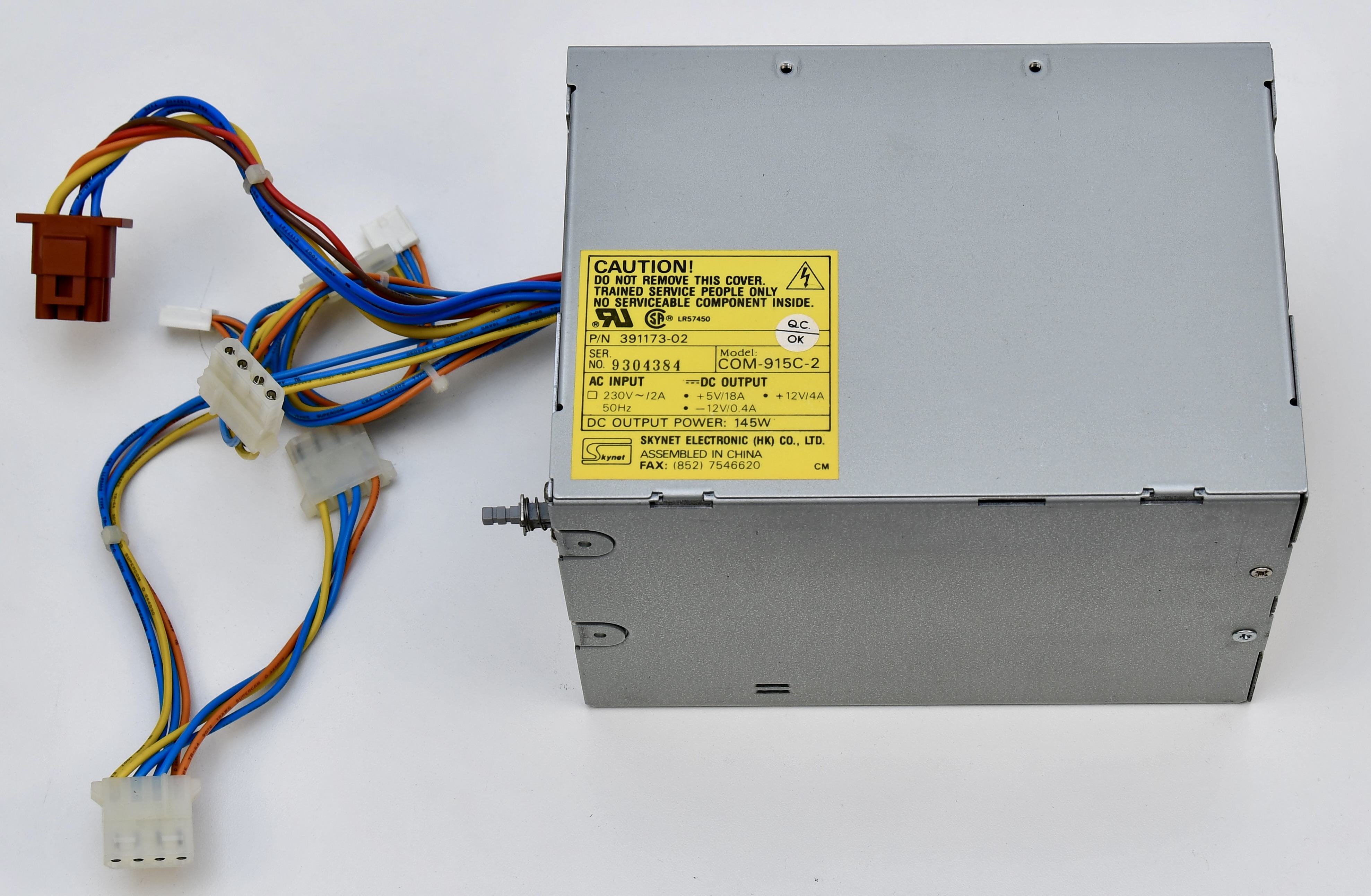
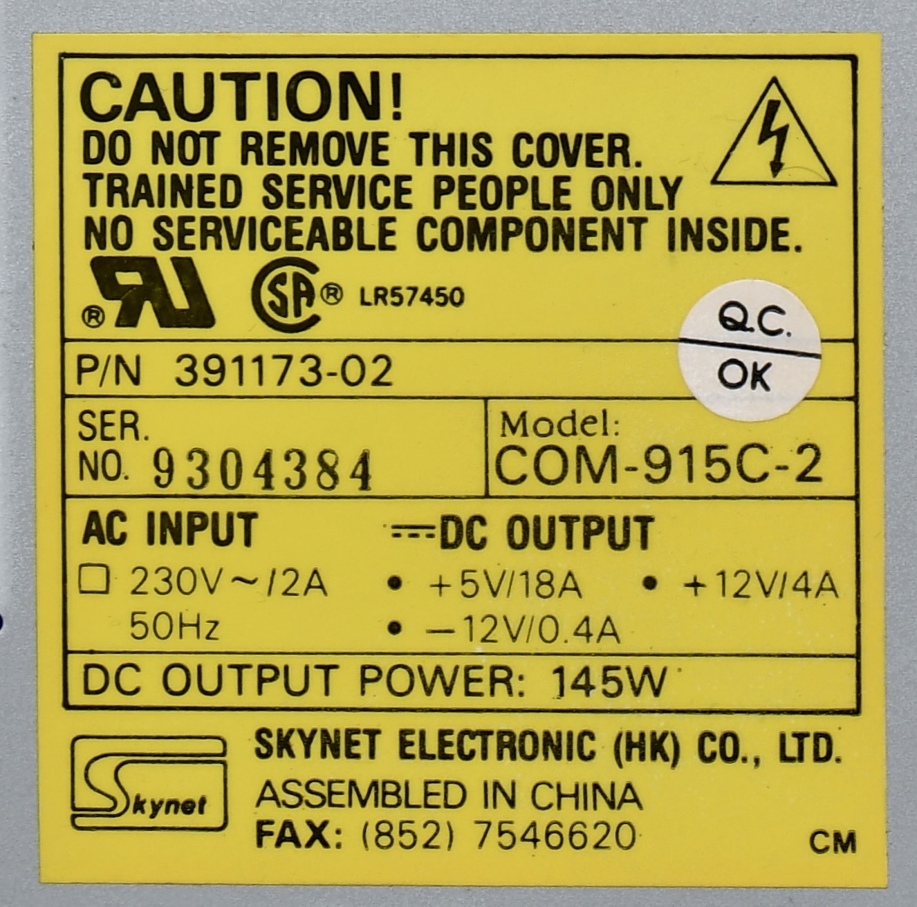
Power Supply
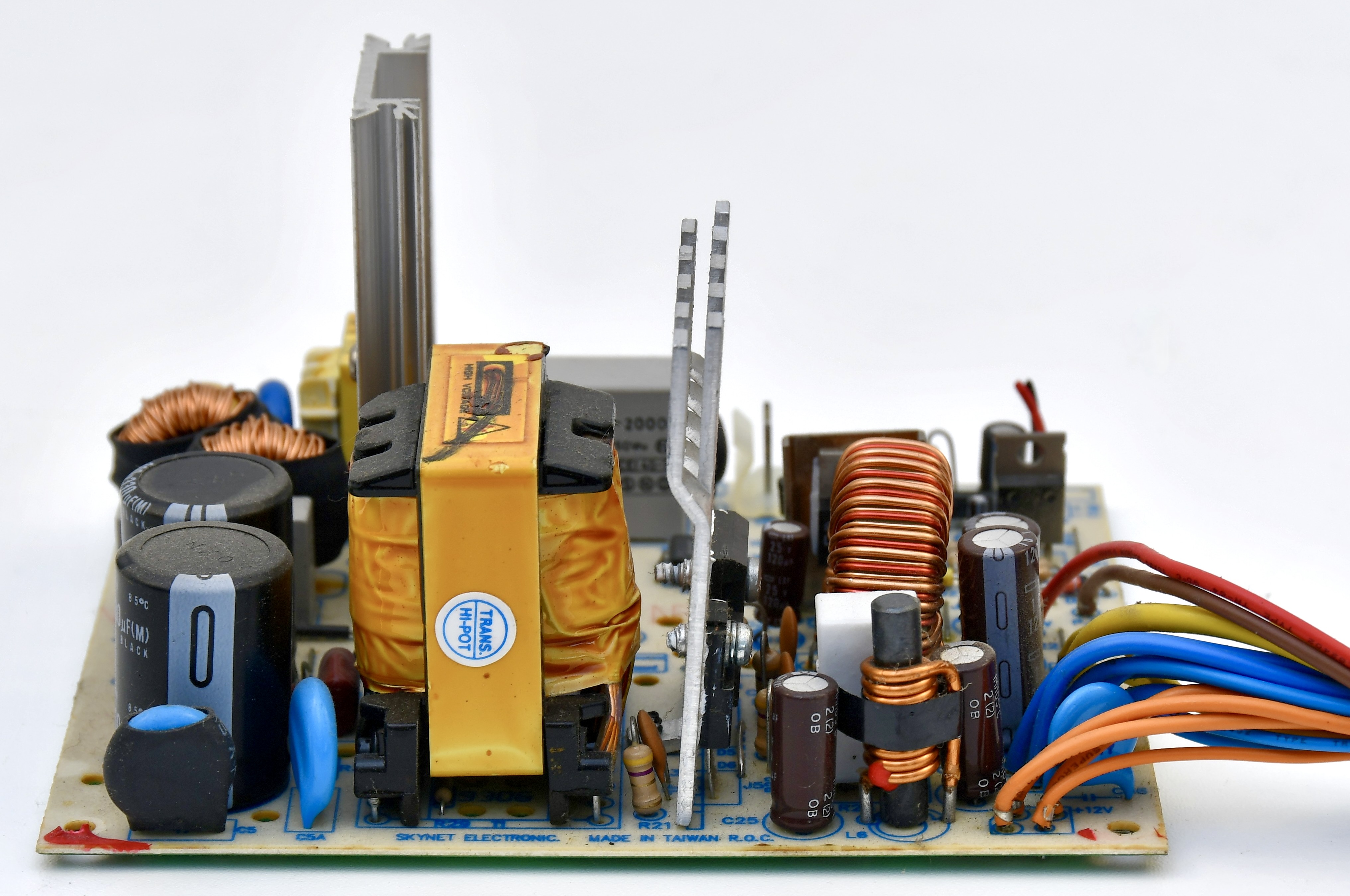
PSU Board


PSU Fan
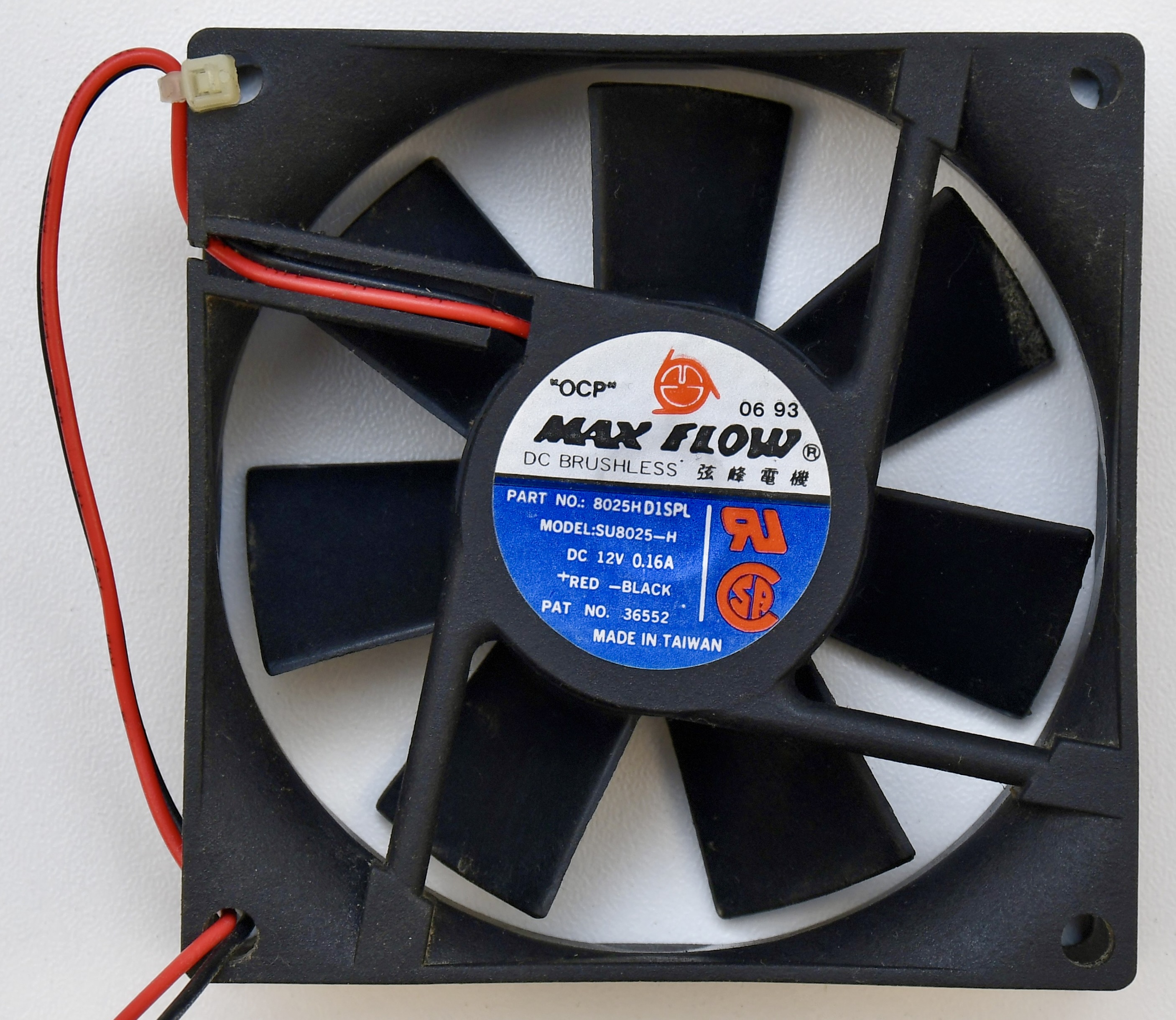

The noisy fan can be replaced with a modern silent fan, for example Noctua NF-R8 Redux 1200, the same which I used in my Amiga 2000 and Amiga 3000.
Case


Fixing CPU Booting Problems on A4000
A few hints what to do when CPU is not booting at all.
- This is at first visible by the power LED not changing brightness on power on.
- Install DiagROM and connect serial cable to a terminal. Confirm there is no output on the serial port, which means either CPU does not start or CIA chip covering serial port is malfunctioning. DiagROM has minimal needs for working hardware to send text over serial port. It needs CPU, ROM and CIA to work. RAM is not required.
- With oscilloscope or state analyser confirm the address and data lines of the CPU are not changing when system is left powered-on.
- With oscilloscope check clock on CPU, on A3630/68030 when internal motherboard clock is used, clocks should be visible on pins CPUCLK_EXP and CLK90_EXP of the CPU board connector. On A3640 or when external clock is used, it should be checked on the accelerator board and EXTCPU, EXT90 pins of the board connector. The clock signal should be stable and it is ok if it has relatively small amplitude, even below 1V (between 3-4V) is ok for CPU to work.
- Check that RESET pin of CPU, visible on _RESET pin of the CPU board connector is brought down from 0 to 1 on system start.
- Check that when _RESET goes up, OVL pin from U350/8520 CIA is set to 1 and is received at Gary/U150. This pin with be automatically set to 1 on system reset and it causes Gary to redirect addresses is the space 0-7FFFF (normally assigned to RAM) to be mapped to ROM. This allows CPU to boot code from ROM.
- When CPU boots, it performs the sequence described in section 7.8 Reset Operation found on page 7-105 of the CPU datasheet.
- CPU executes RESET Exception described in section 8.1.1 Reset Exception.
- It attempts to asynchronously read two long words from the bus at addresses 0 and 4. These long words are the first two words in ROM and contain the interrupt stack pointer and program counter for the CPU to start from.
- The read operations will follow the chart described on Figure 7-19. Asynchronous Long-Word Read Cycle Flowchart
- We should observe the timings presented on Figure 7-23. Long-Word Read — 16-Bit and 32-Bit Port (long word part – first S0-S4 bus clock cycles)
- A31-A2 should be zero for the first read and for the second A2 should go to 1
- A1-A0 should be zero for both reads (aligned reads)
- FC2-FC0 should be 110 – Supervisor Program Space
- Check all the other signals that they match the chart: SIZ1/0, R/W, ECS, OCS, AS, DS, DSACK1/0, DBEN and all data bits.
- Any signals that are not within digital levels spec, i.e. close to 5V for 1 and close to 0V for 0, can indicate that there is some problem that can be the cause for the processor to hang during bus operation. I don’t know the tolerance for 68k CPU, but it can be figured out easily when looking at all signals – most of them will look the same, except the faulty ones.
- Using schematics and PCB Explorer, trace the faulty signals and find the problem – broken trace, malfunctioning chip or something else.
- In my case, there was U891/74F245 data buffer to fast RAM malfunction and D6-D3 signals were oscillating around 3V. This caused the CPU to hang and set most of signal lines to 1 during the first long word read operation. Replacing the chip fixed the problem.
Reassembly


