


Resources
Documents
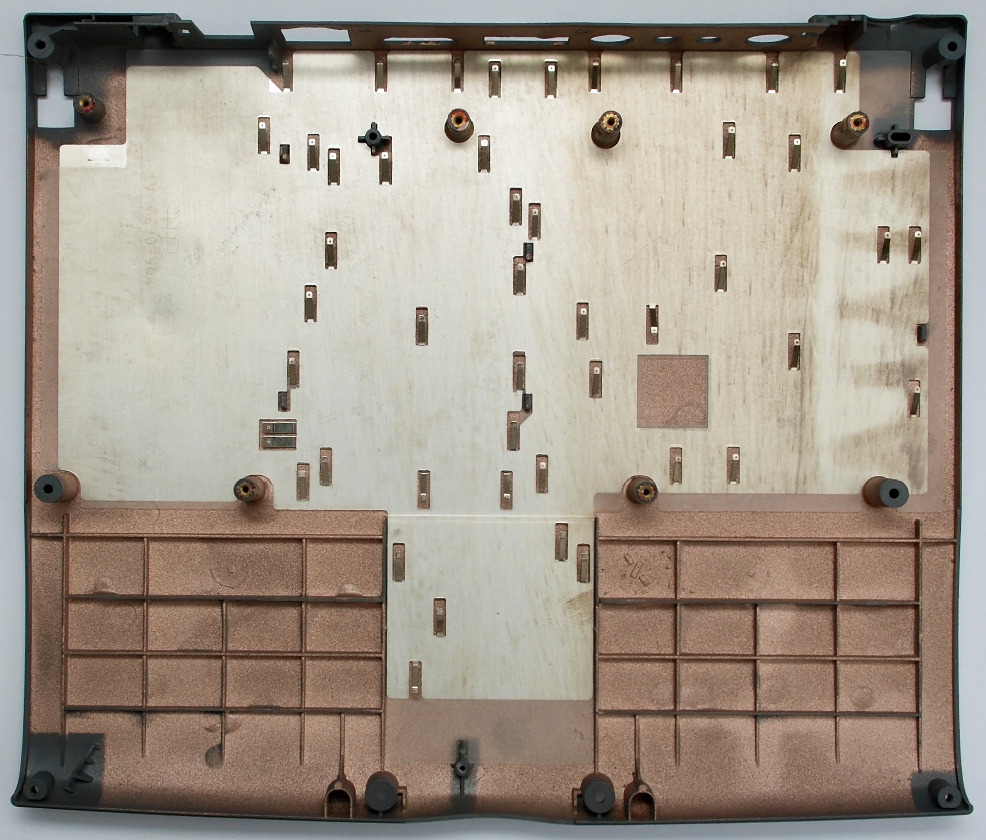
Internals
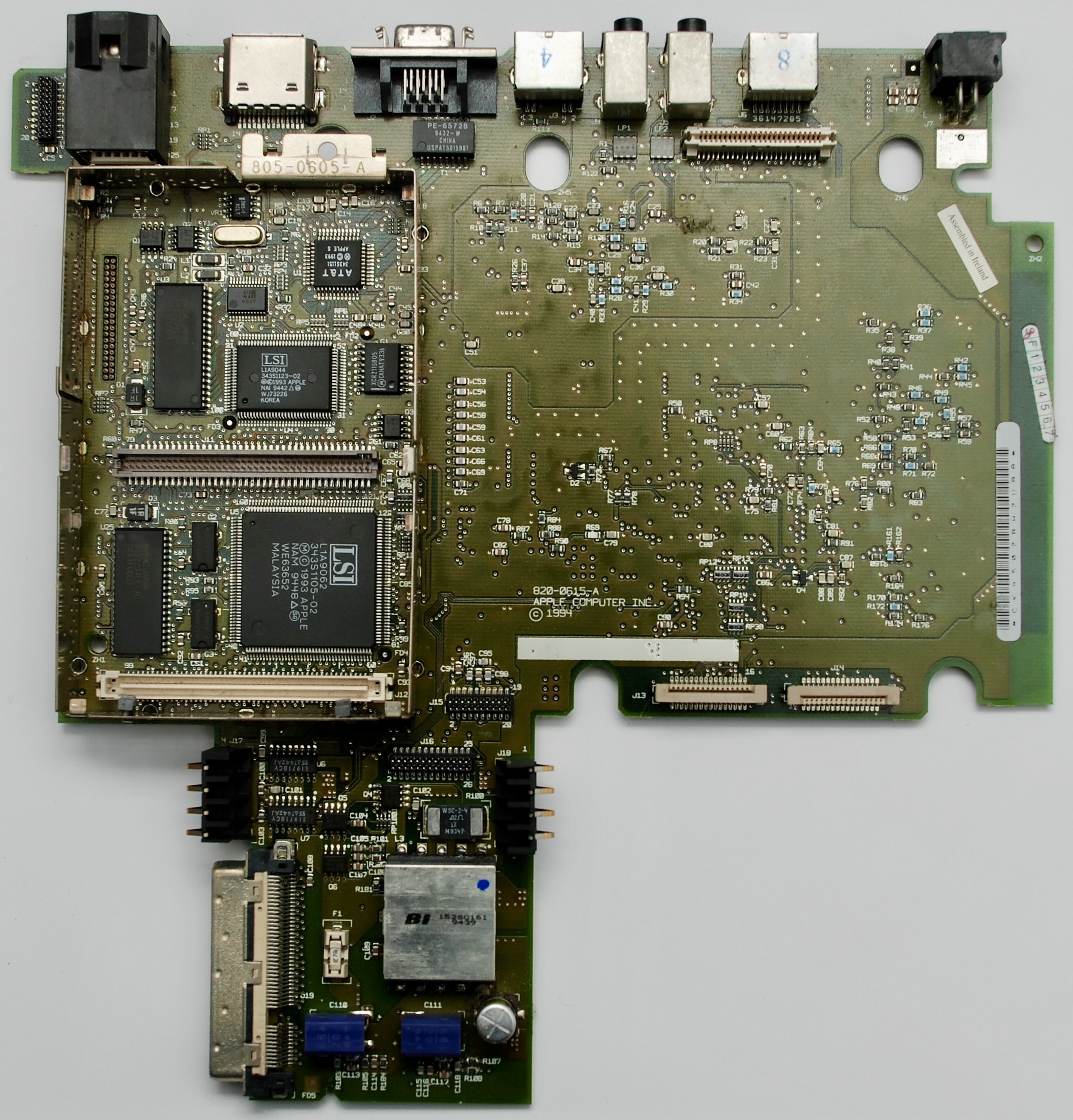
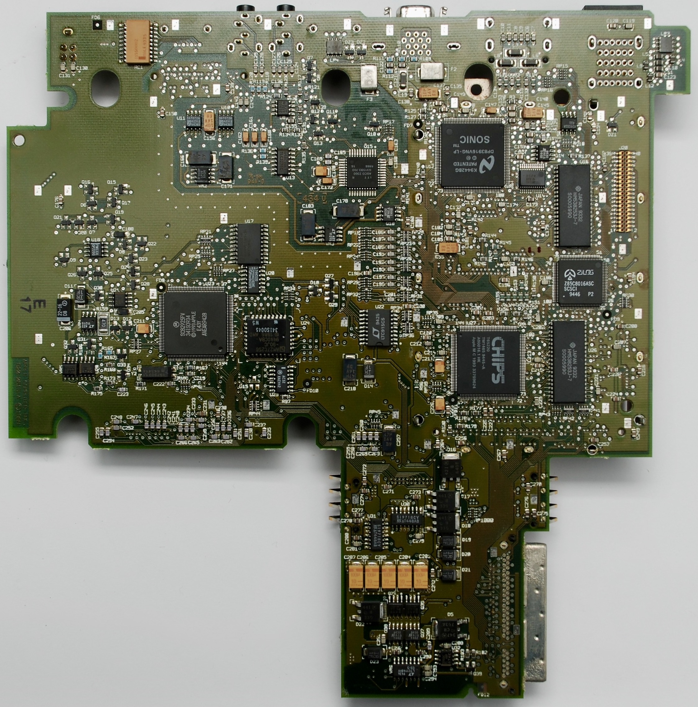
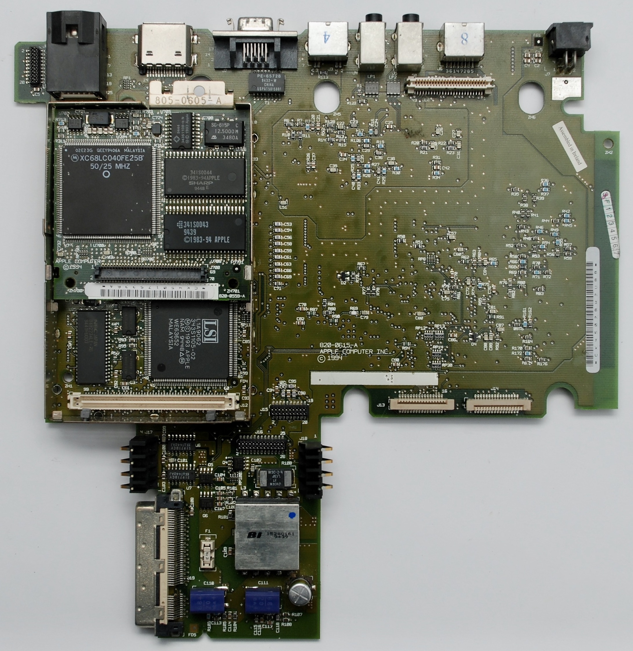
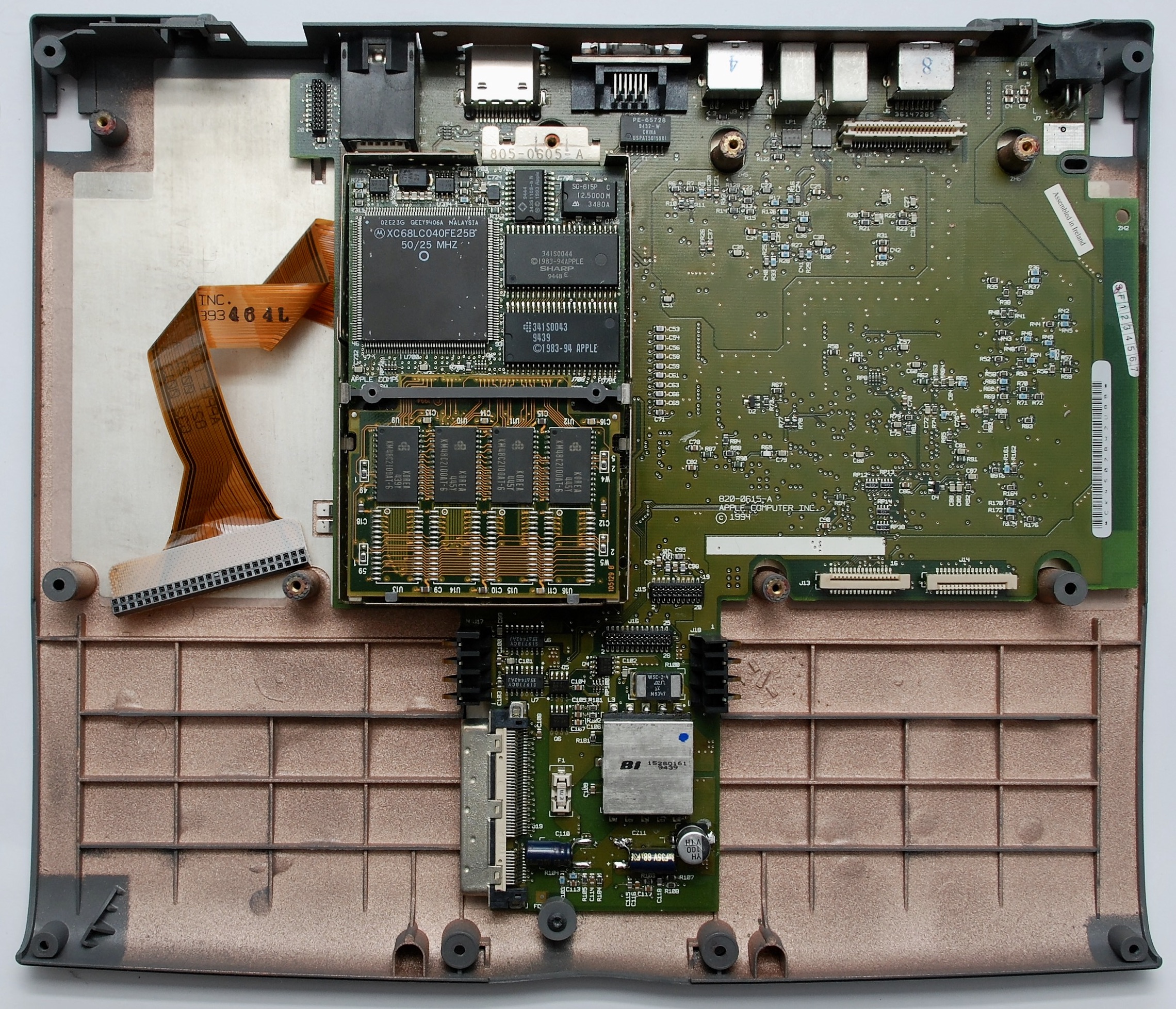
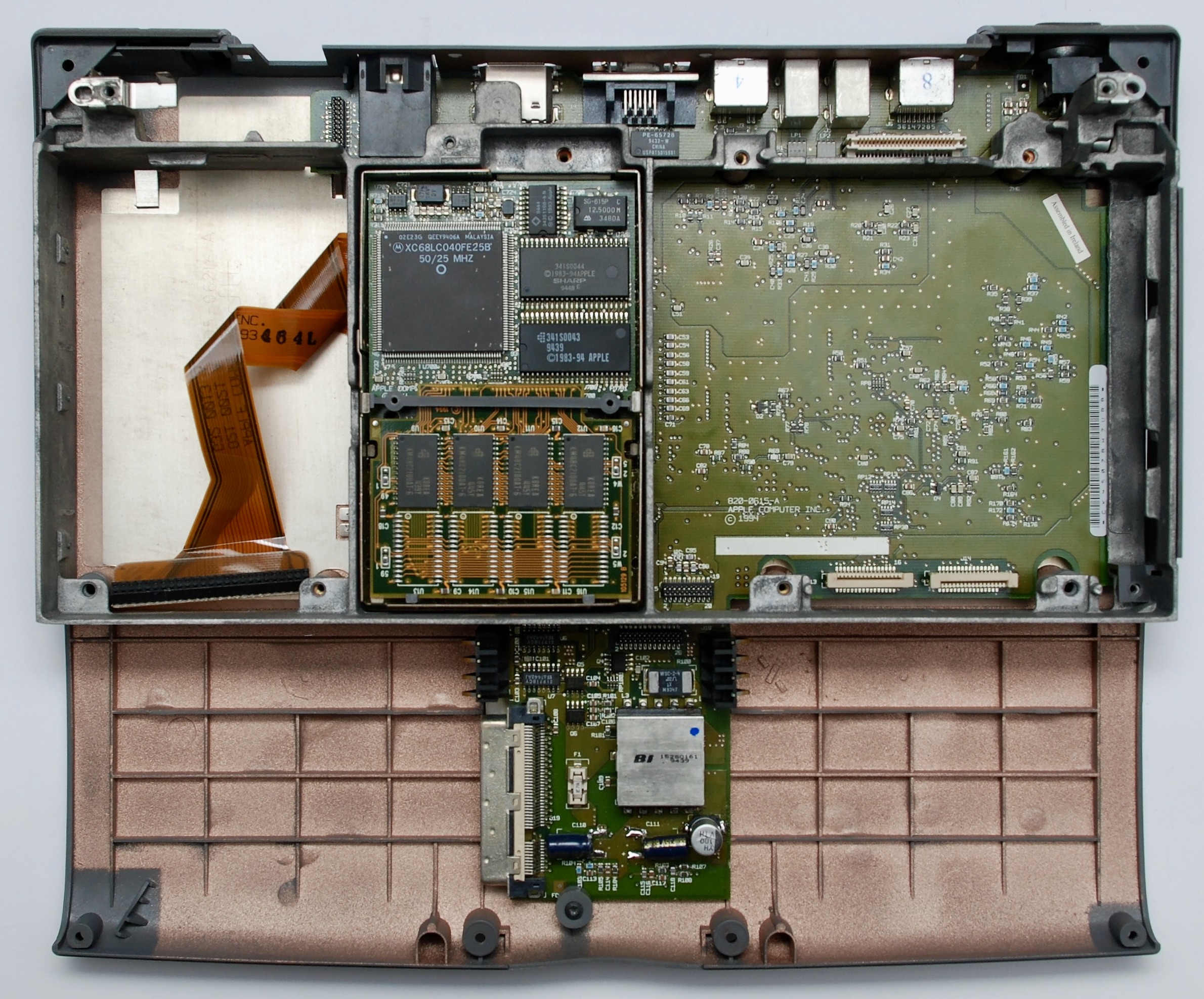
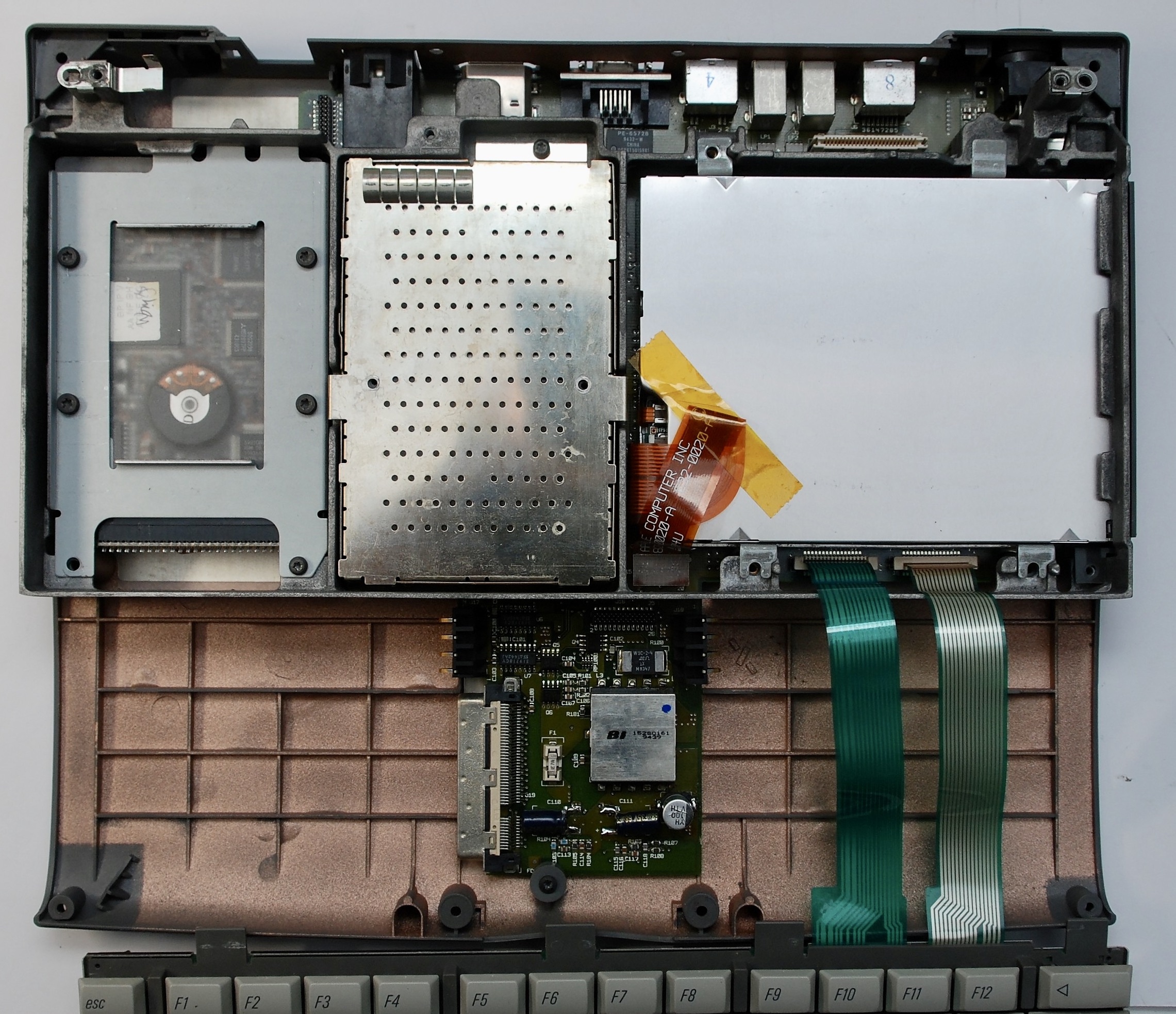
Motherboard


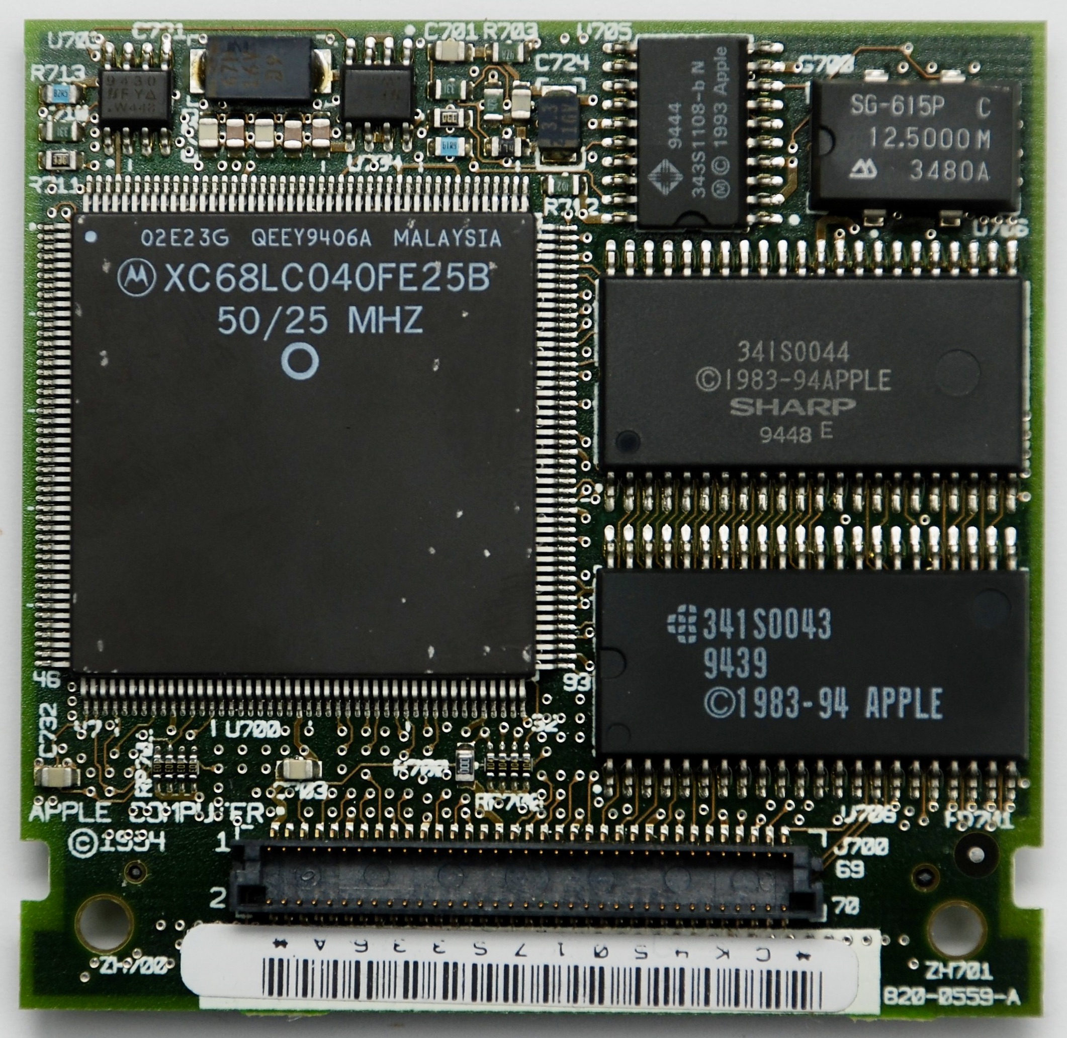
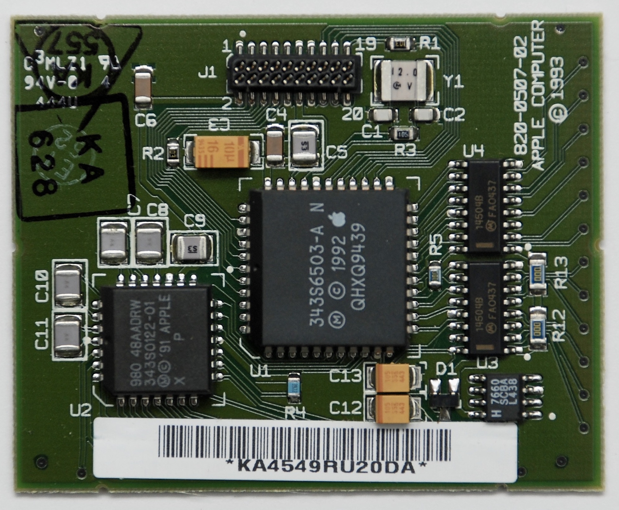
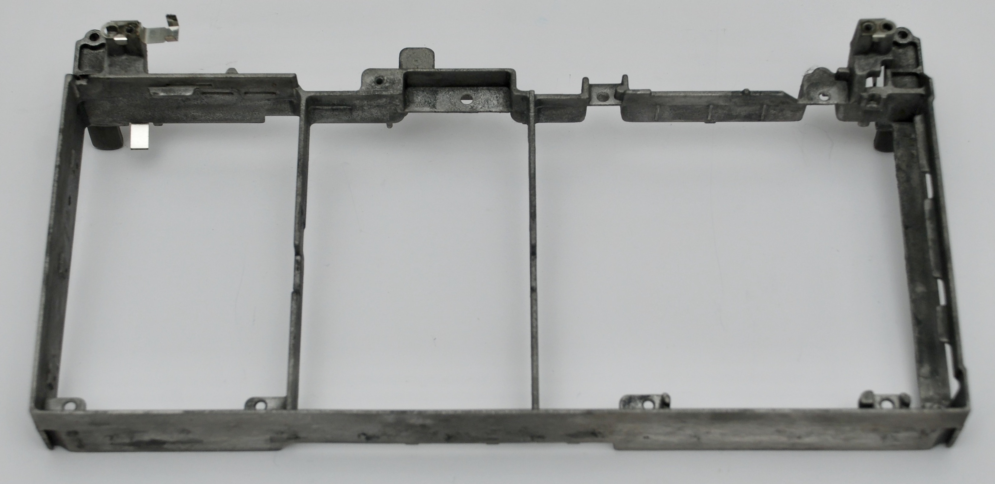
CPU Board
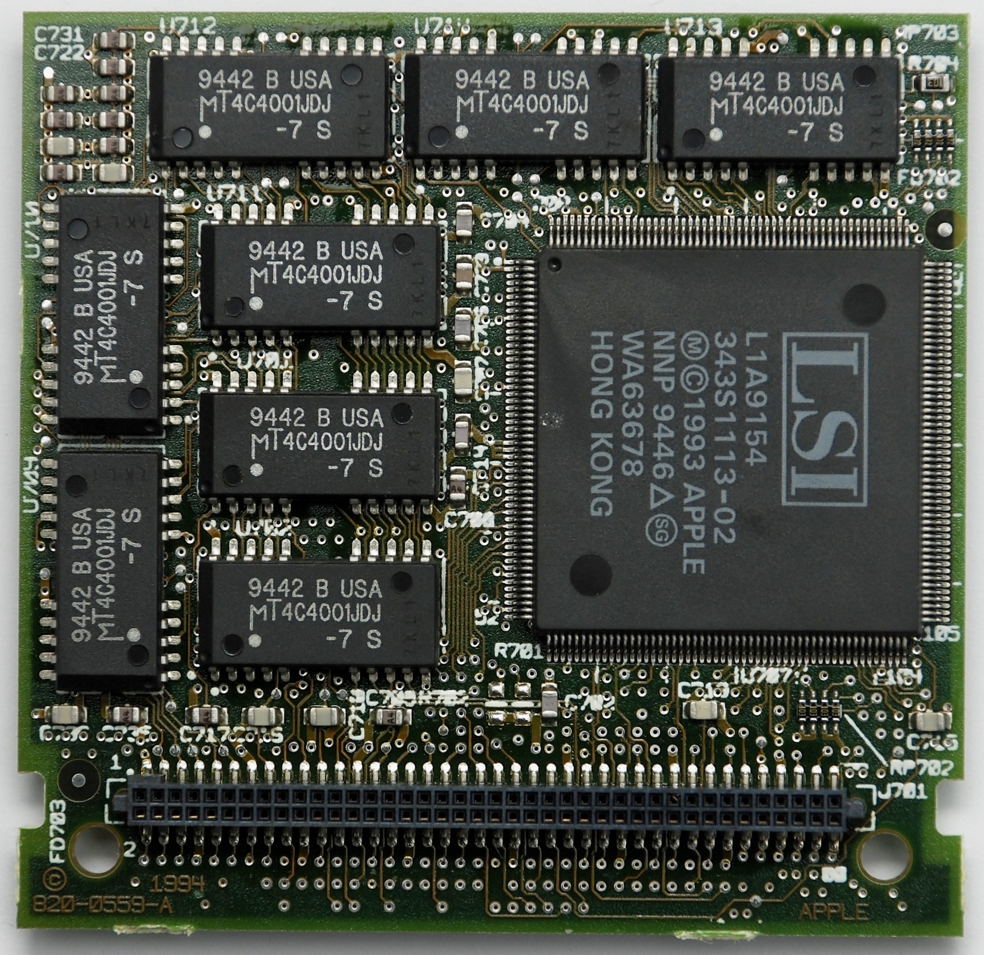
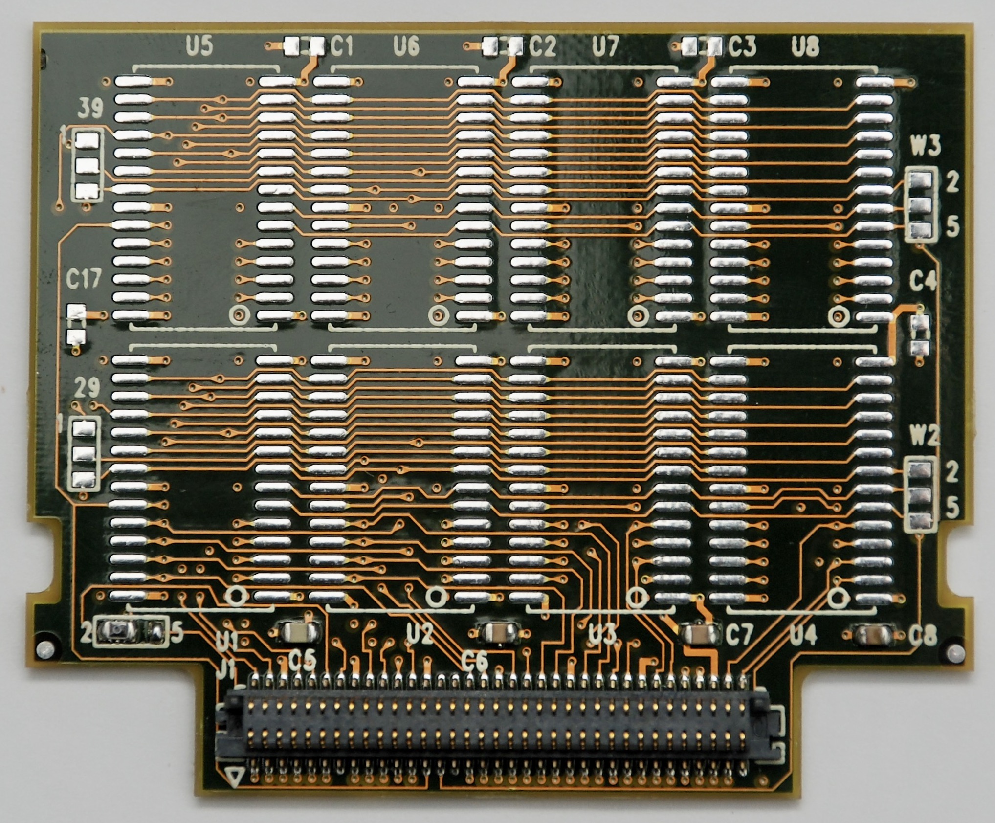
Memory Extension Board

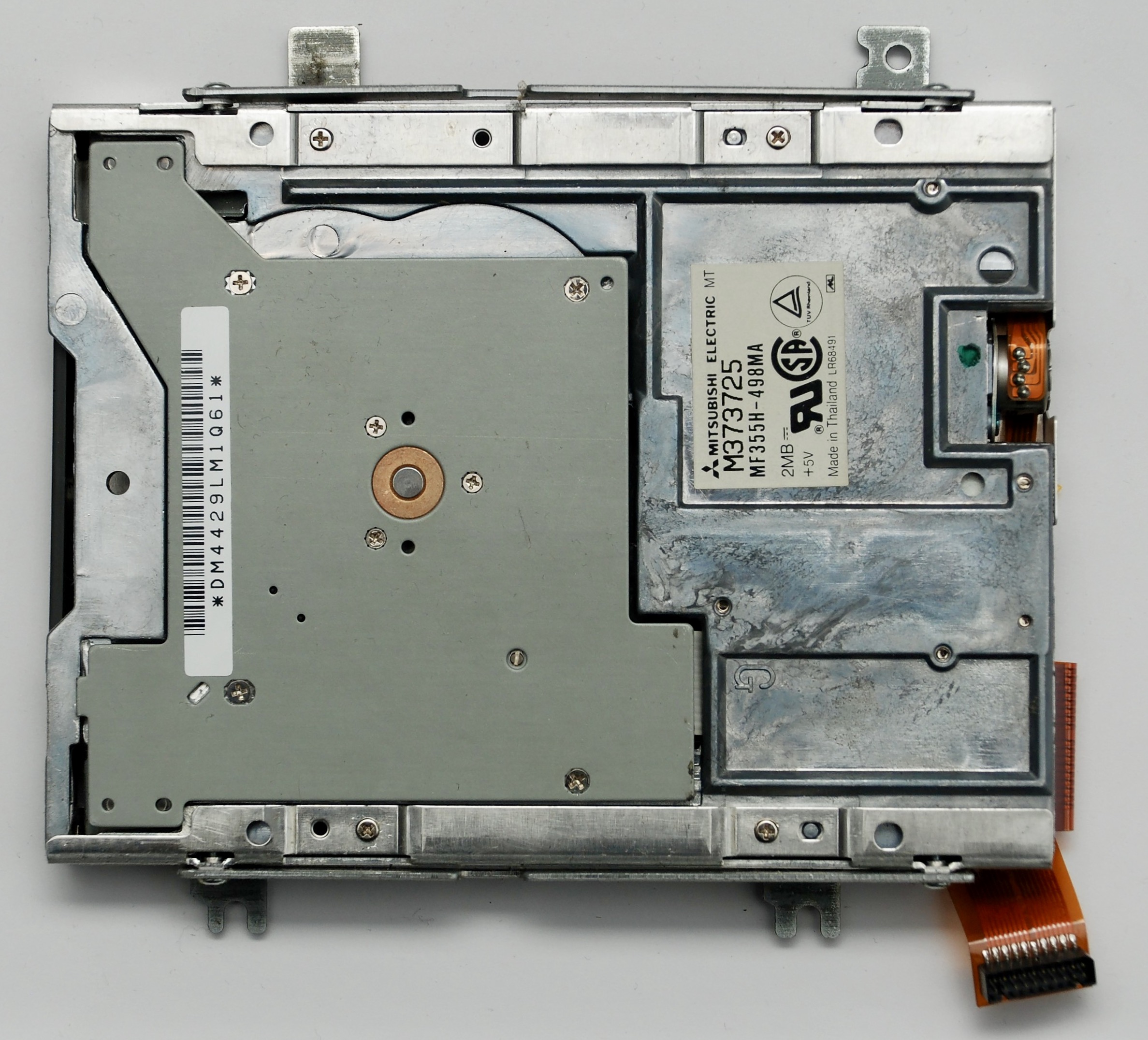
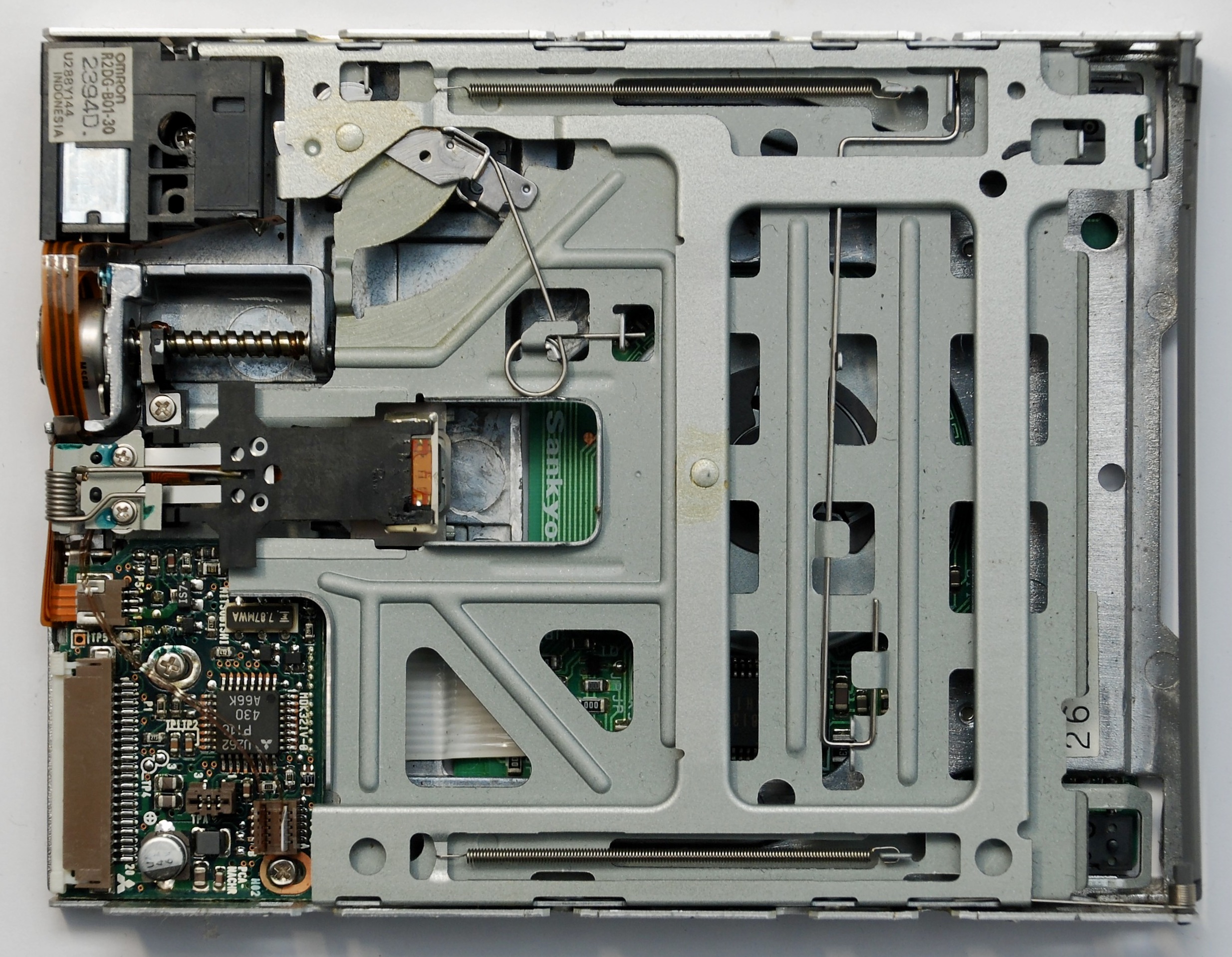
Floppy Disk Drive
Mitsubishi Electric MF355H-498MA

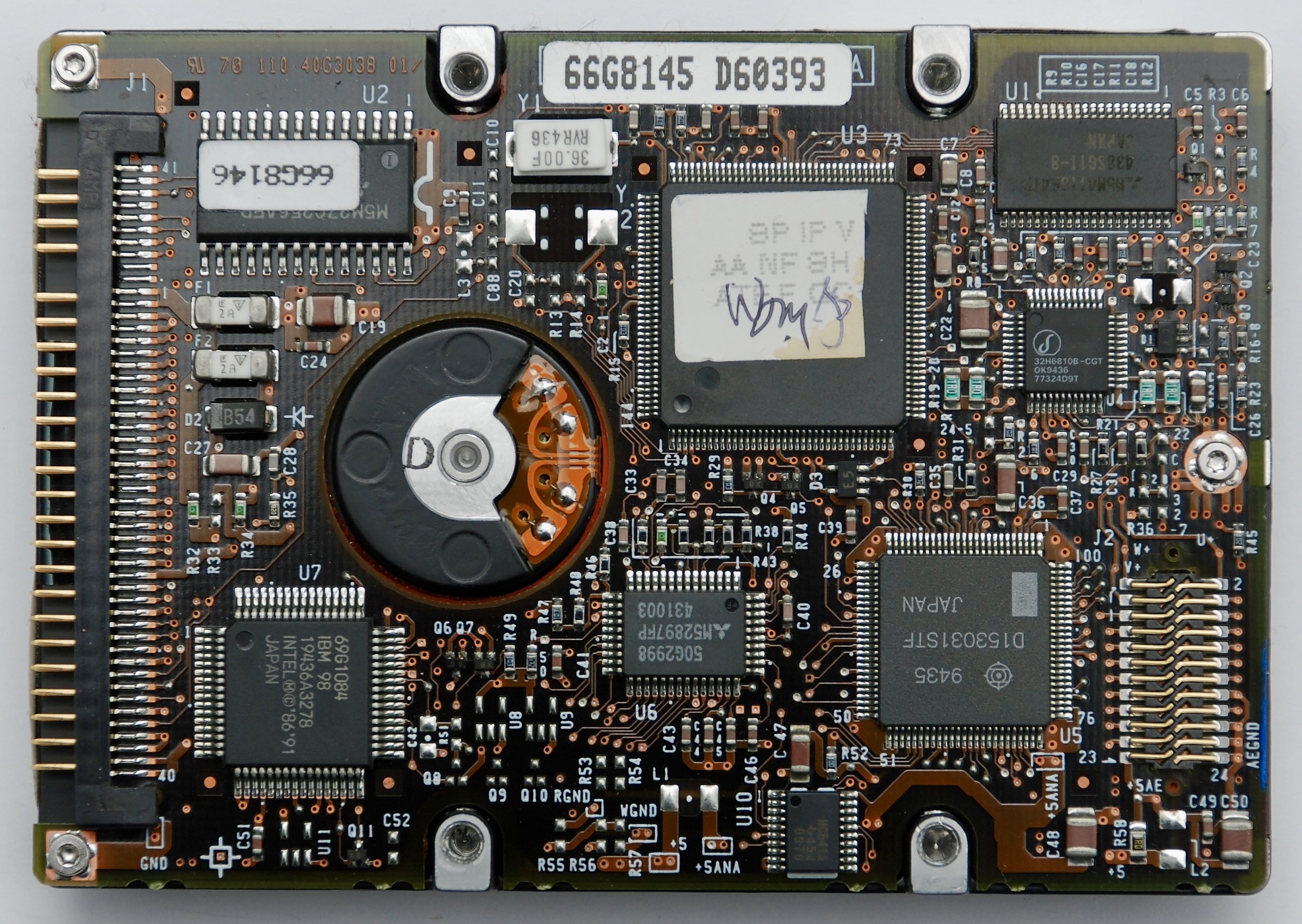
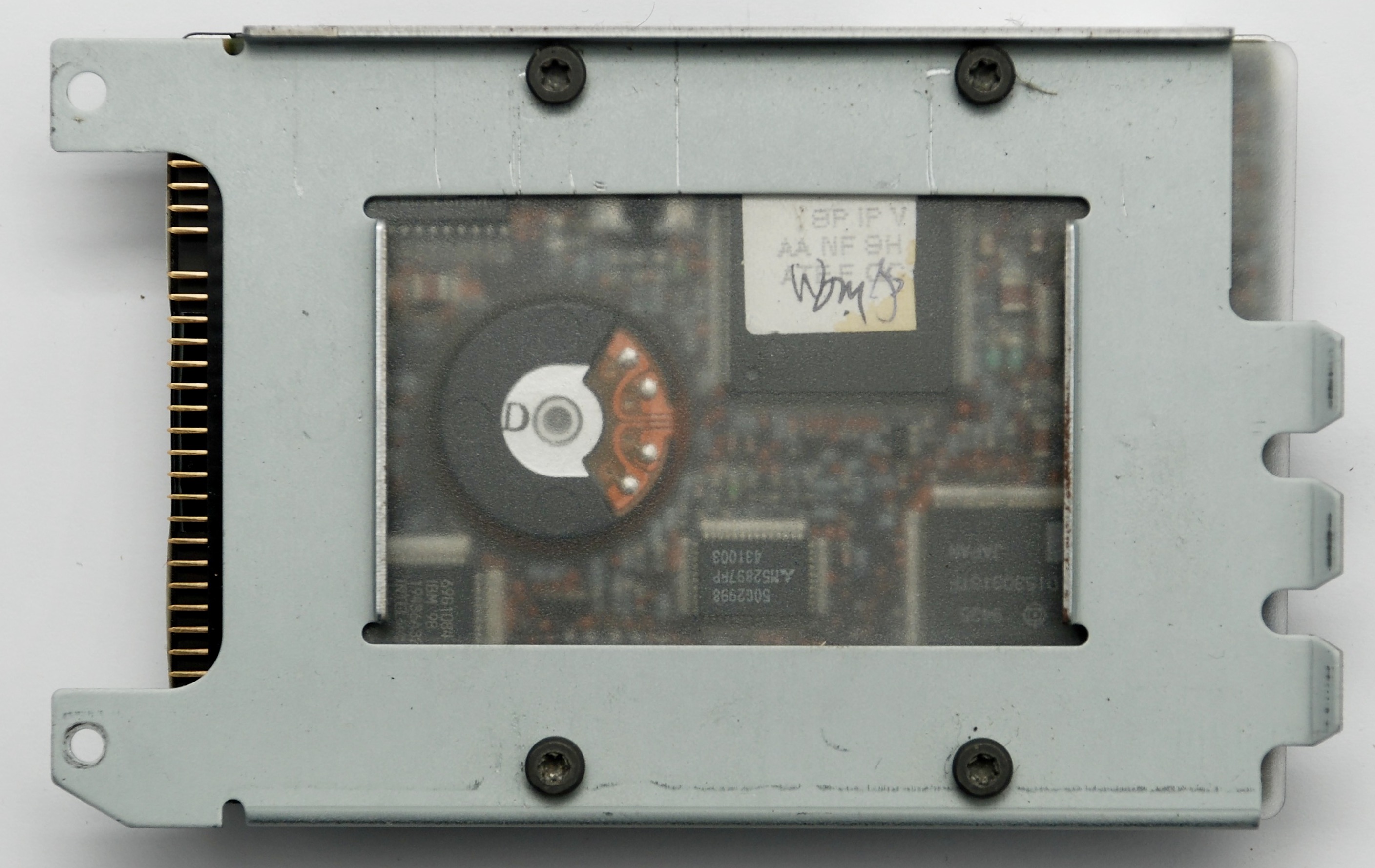
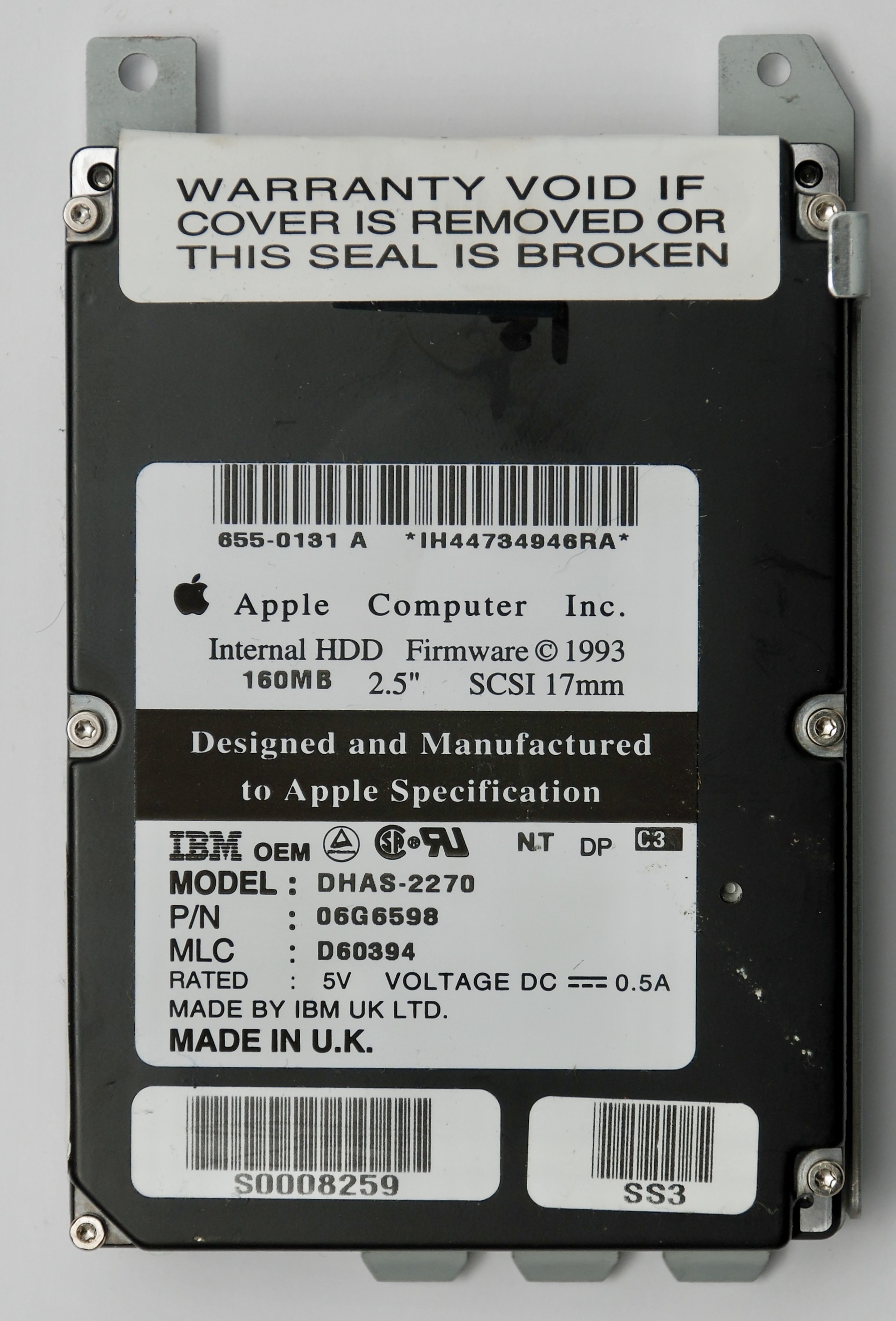
Hard Disk Drive
160MB SCSI IBM DHAS-2270

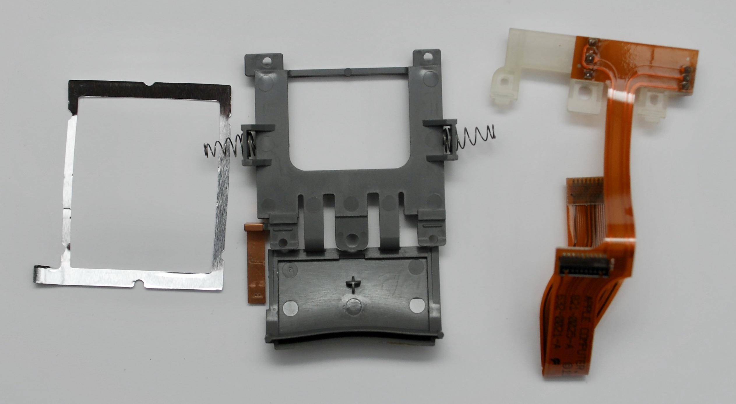
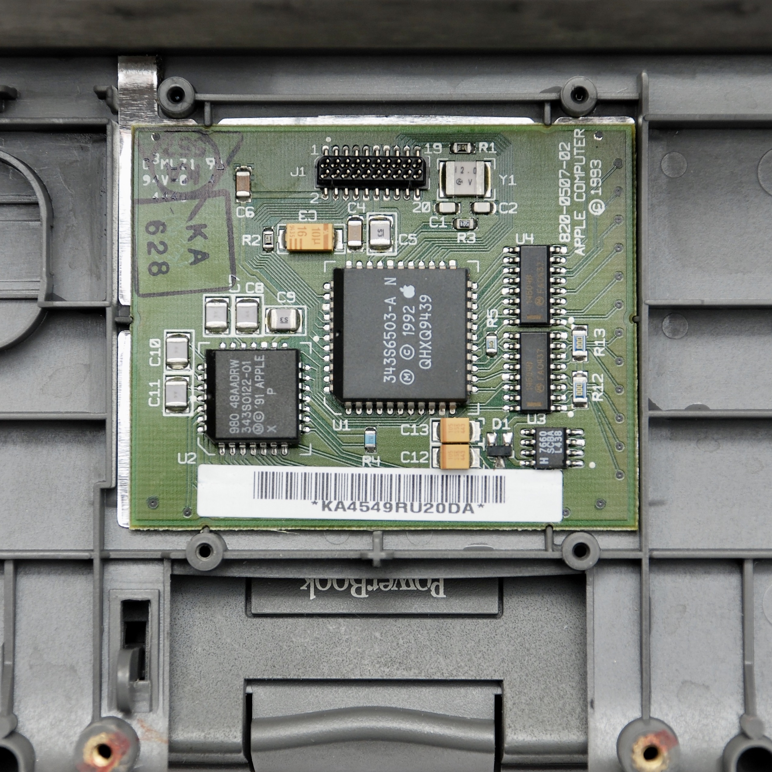
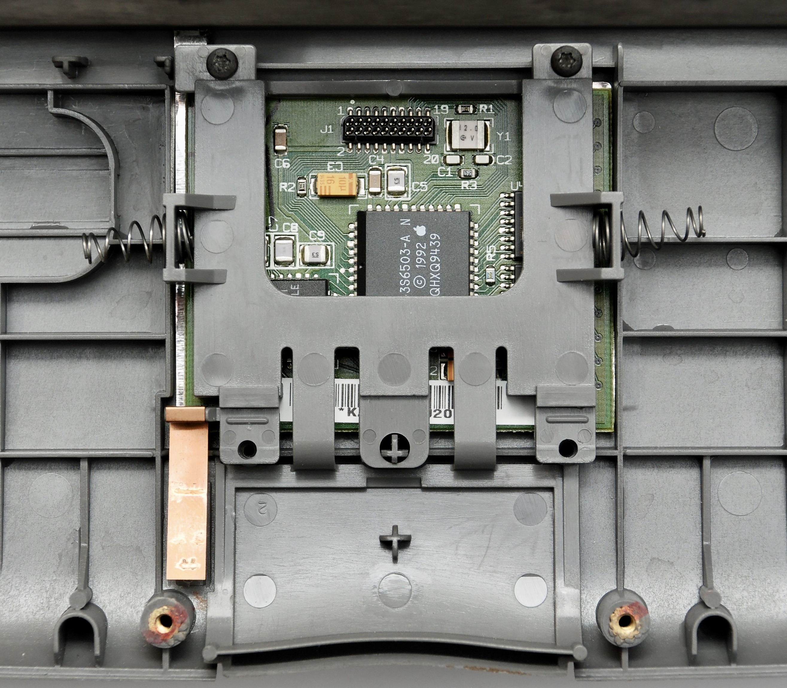
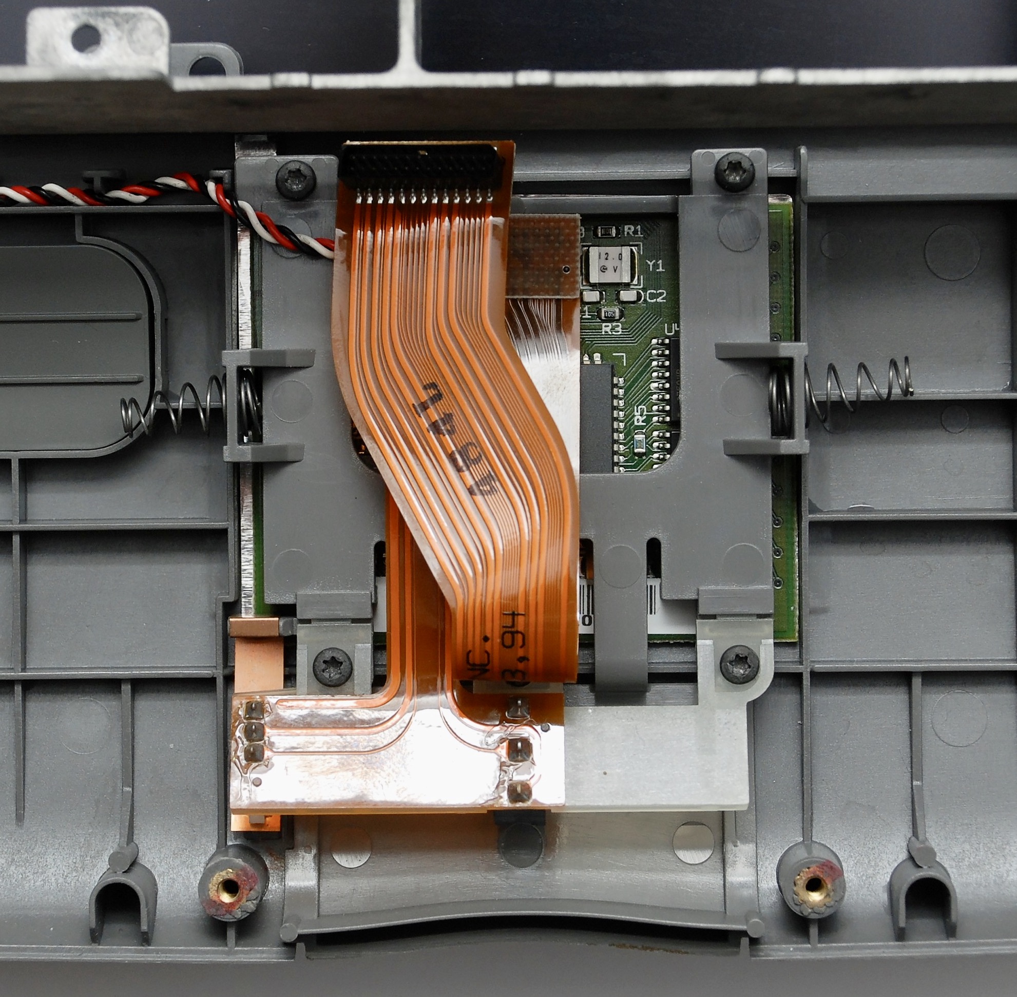
Touchpad
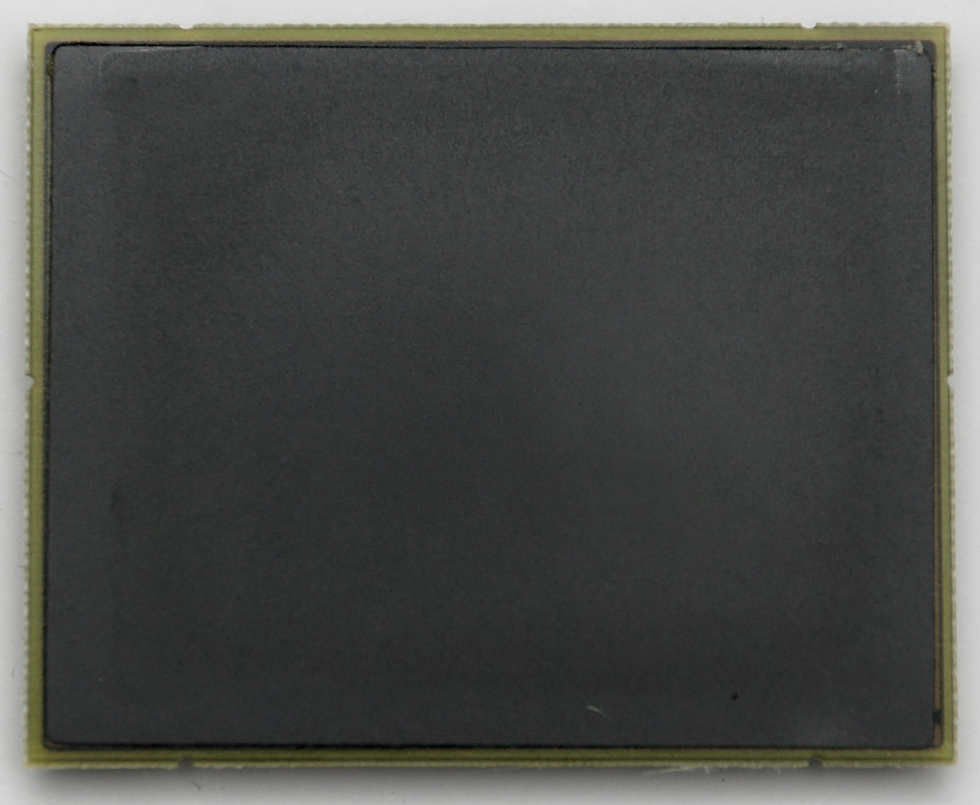
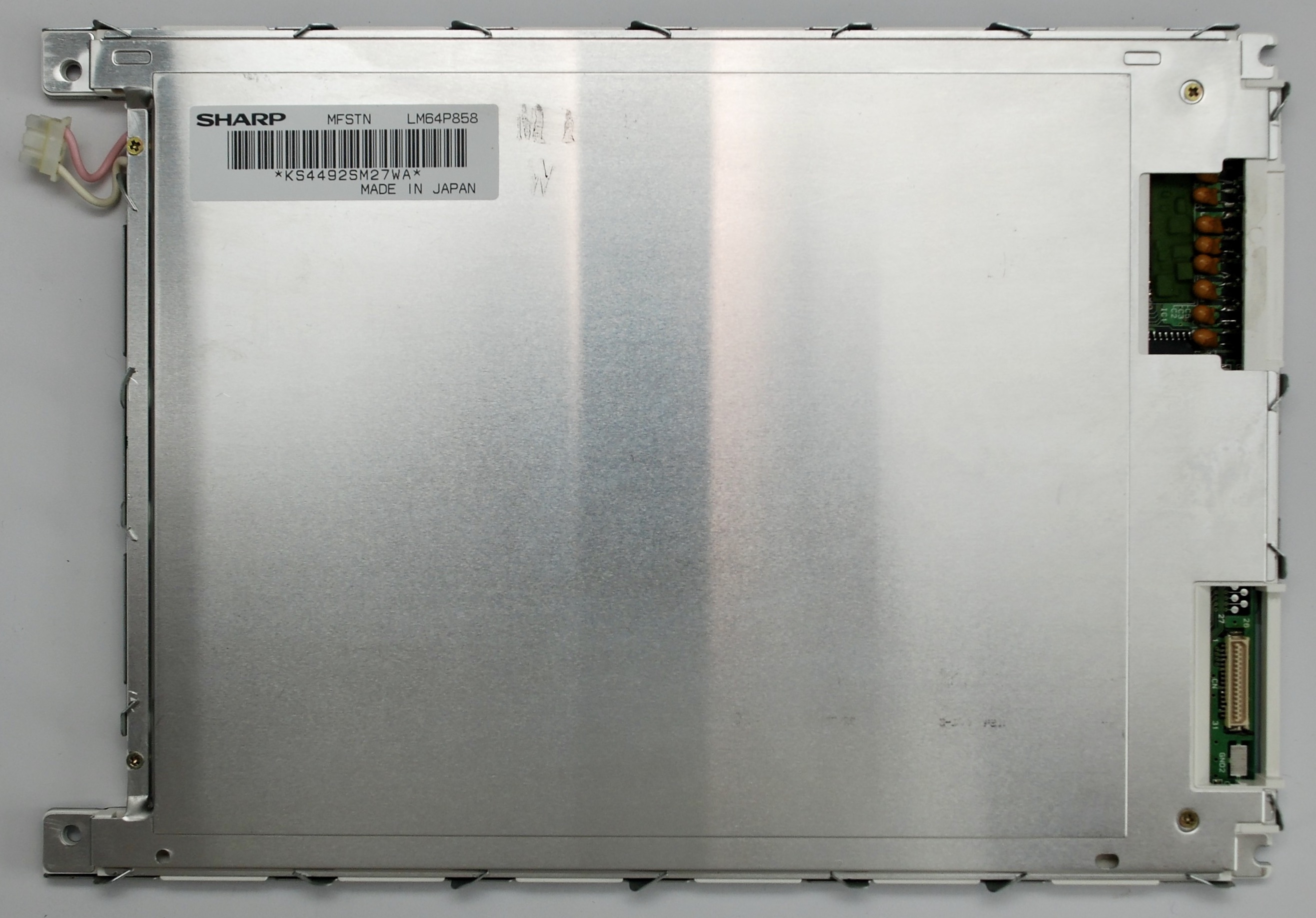
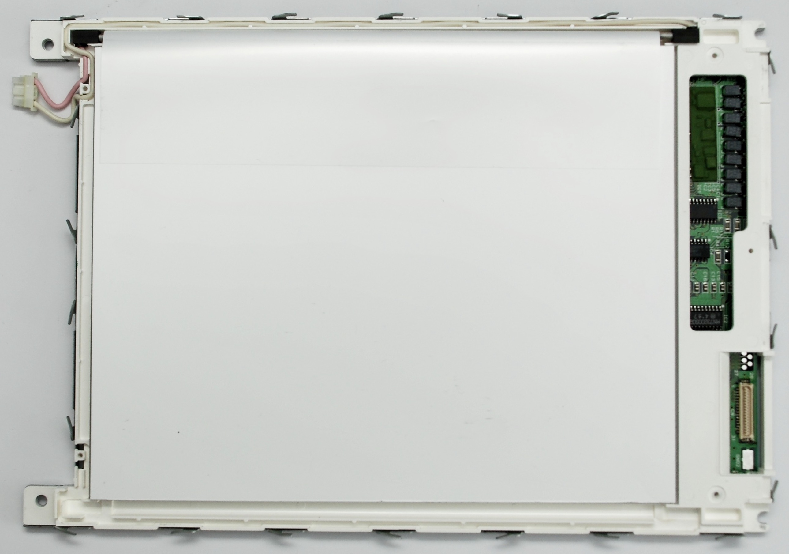
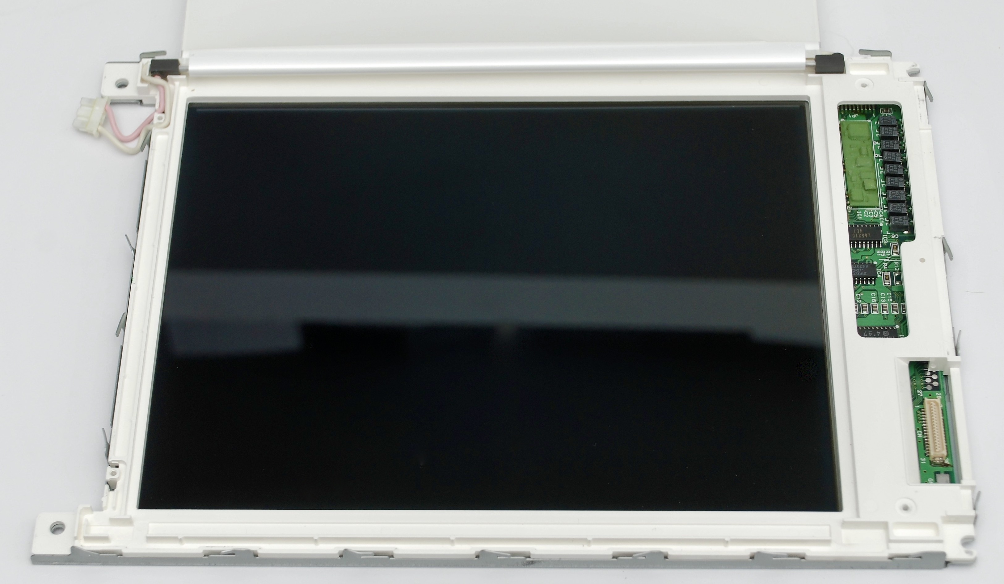
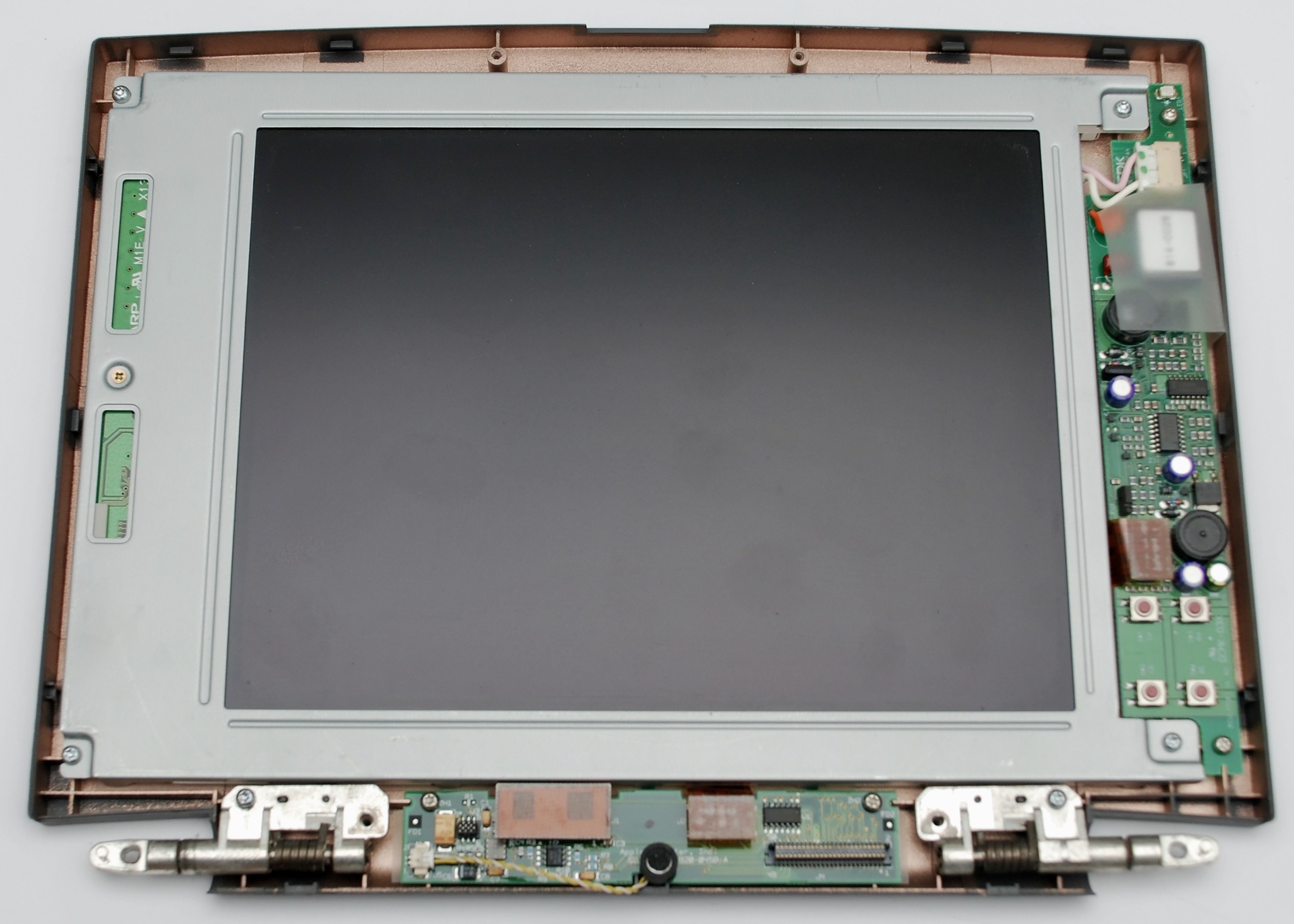
Display
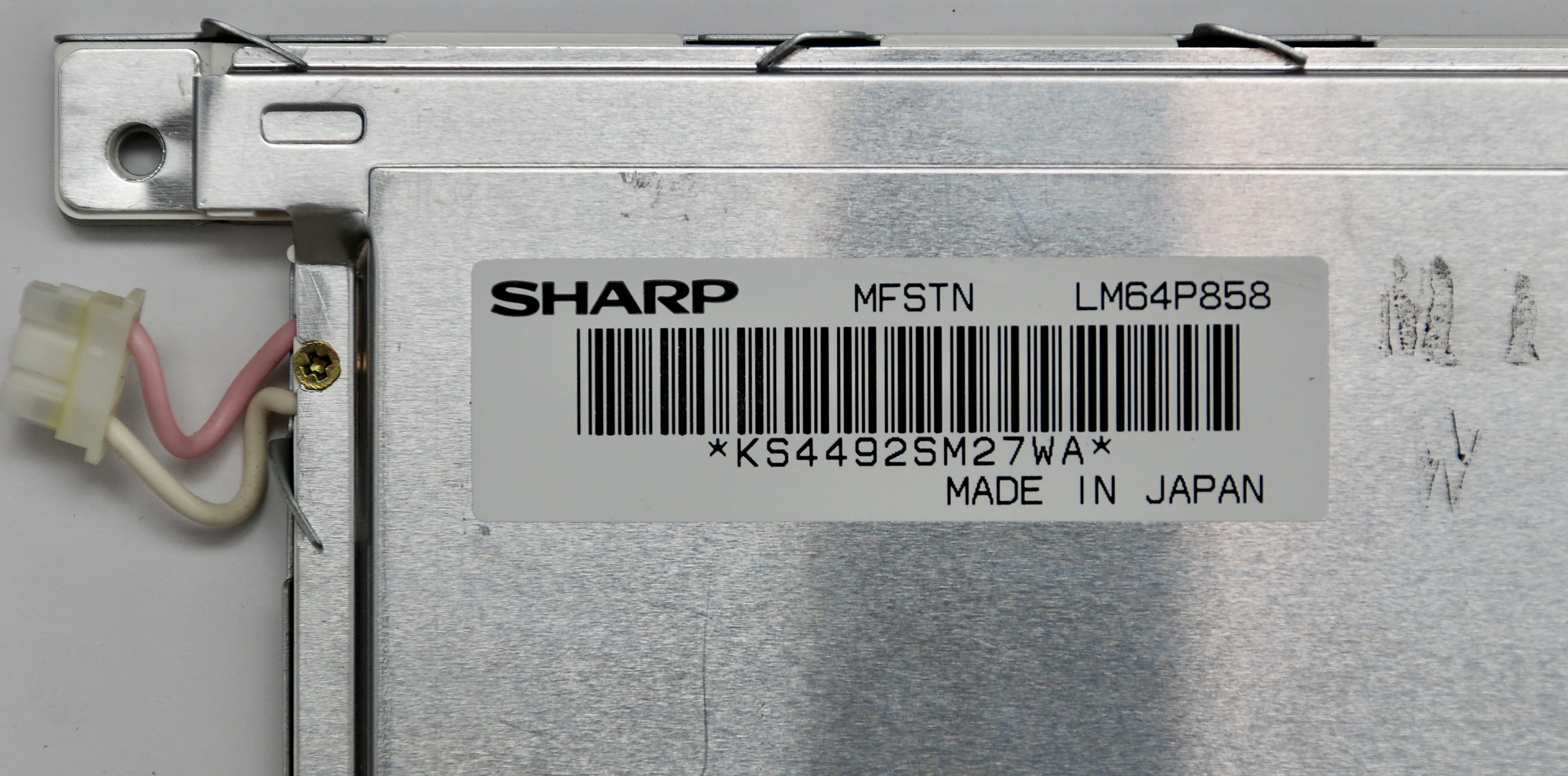
Sharp MFSTN LM64P858
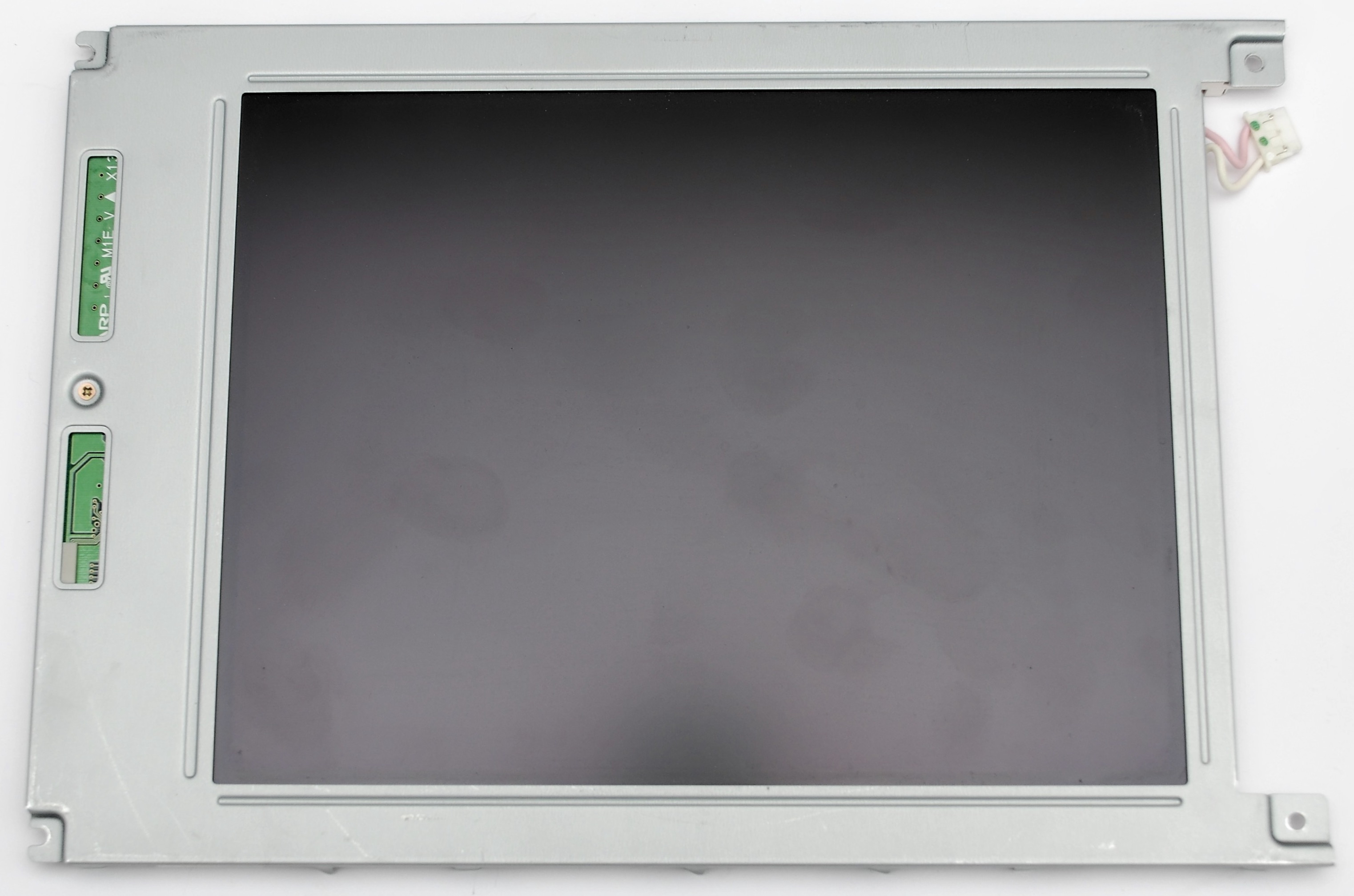

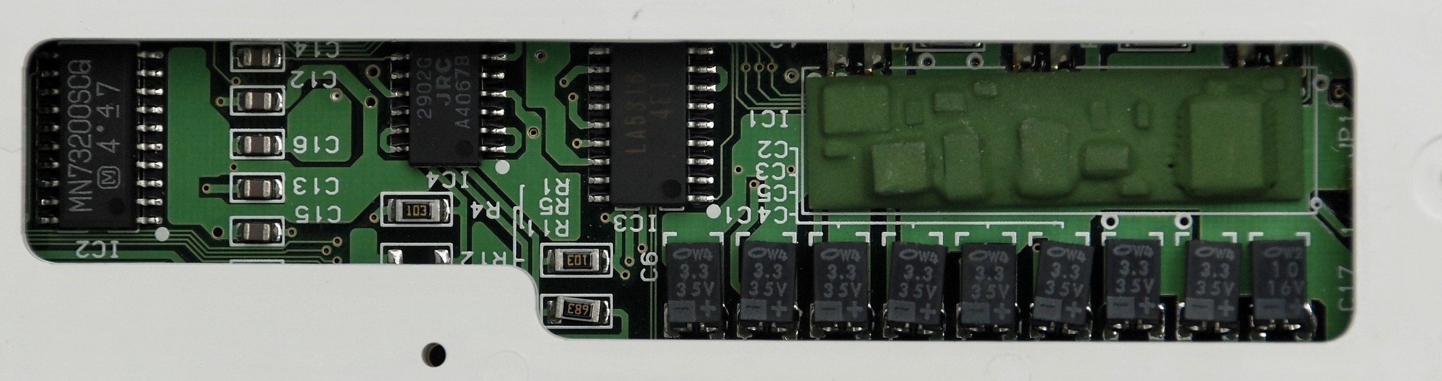
Before and after replacing electrolytic capacitors

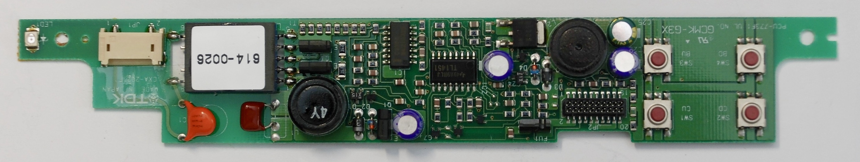
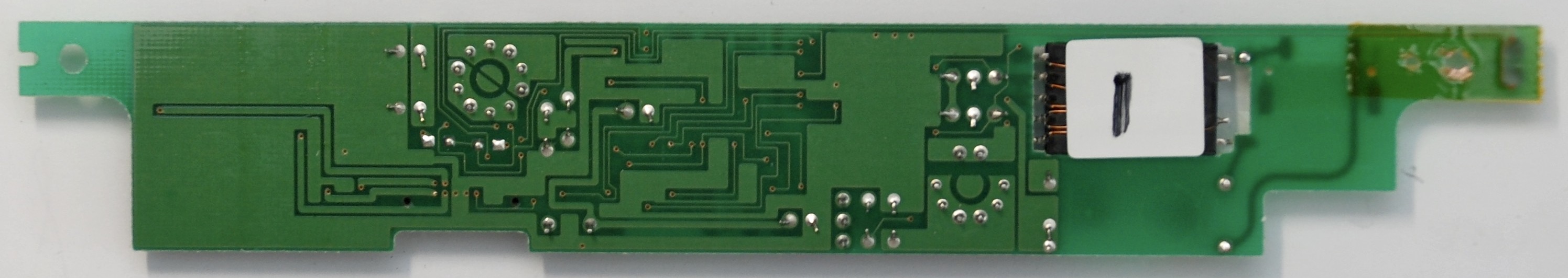
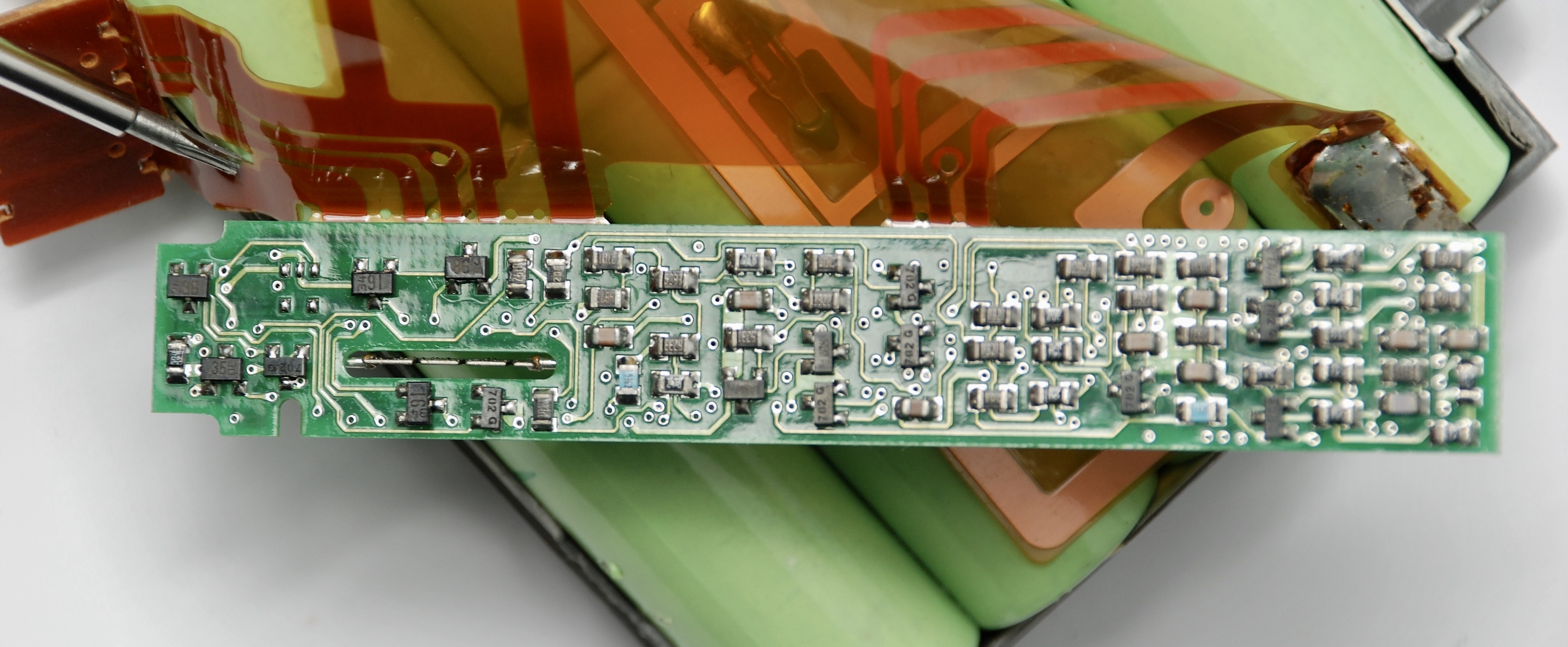
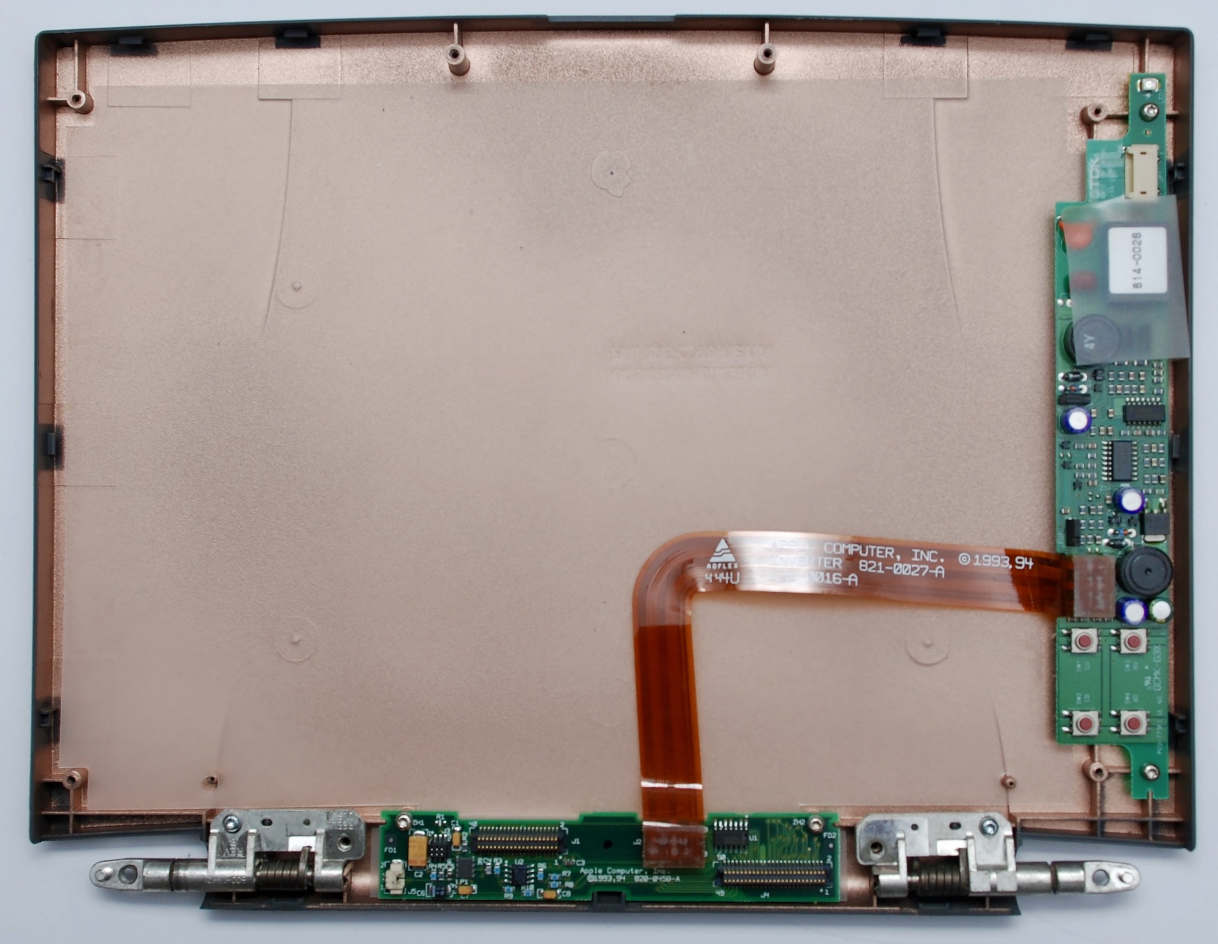
Backlight Inverter Board
TDK CXA-2021F1
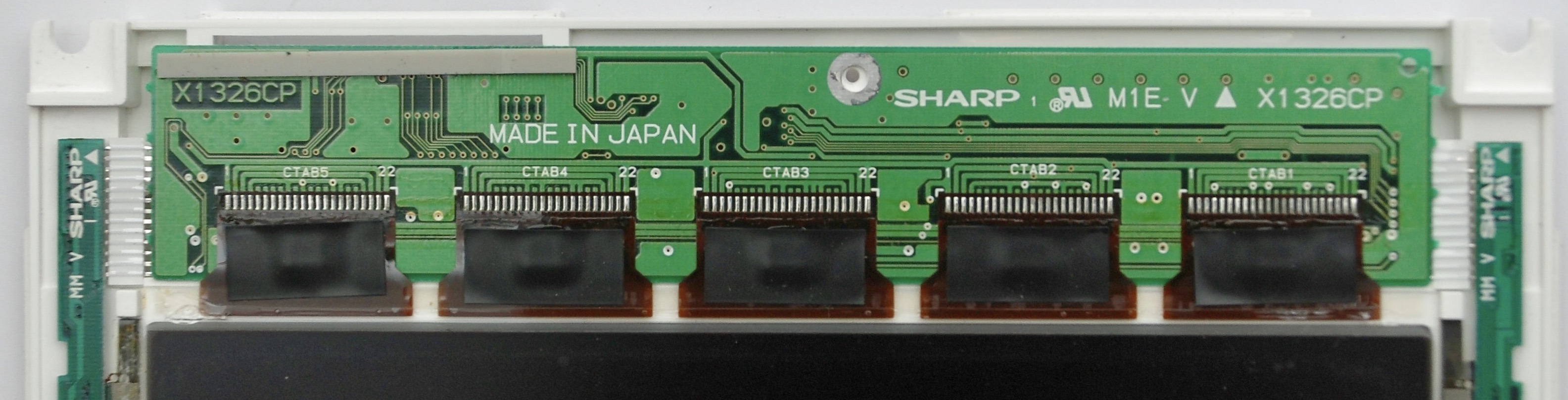
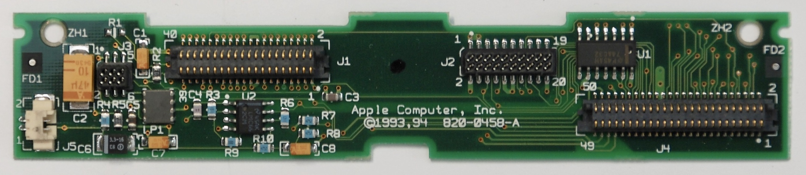
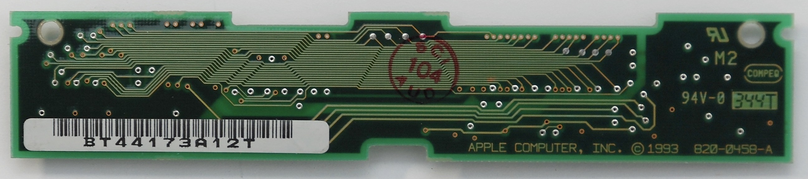
Display Interconnect Board
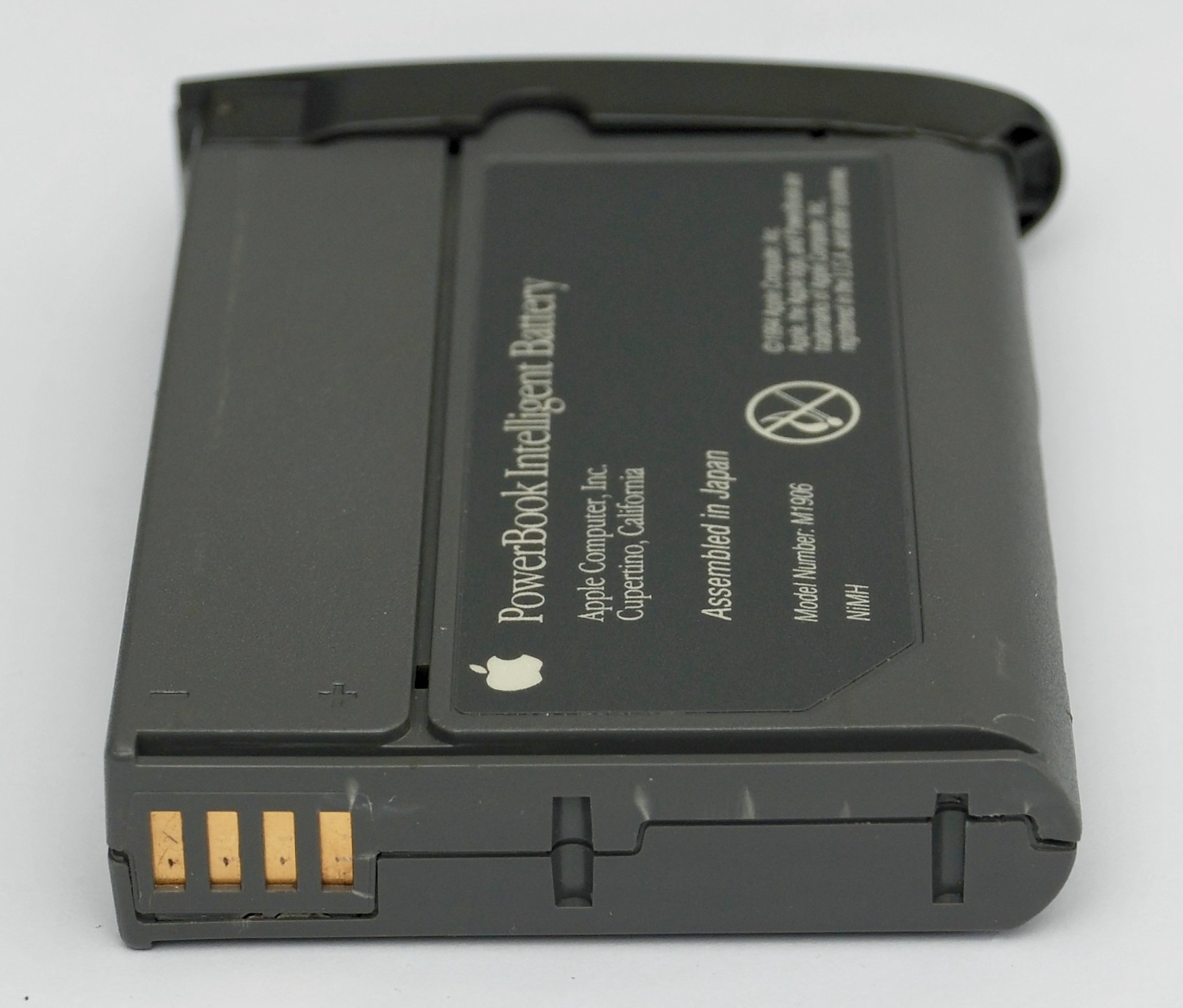
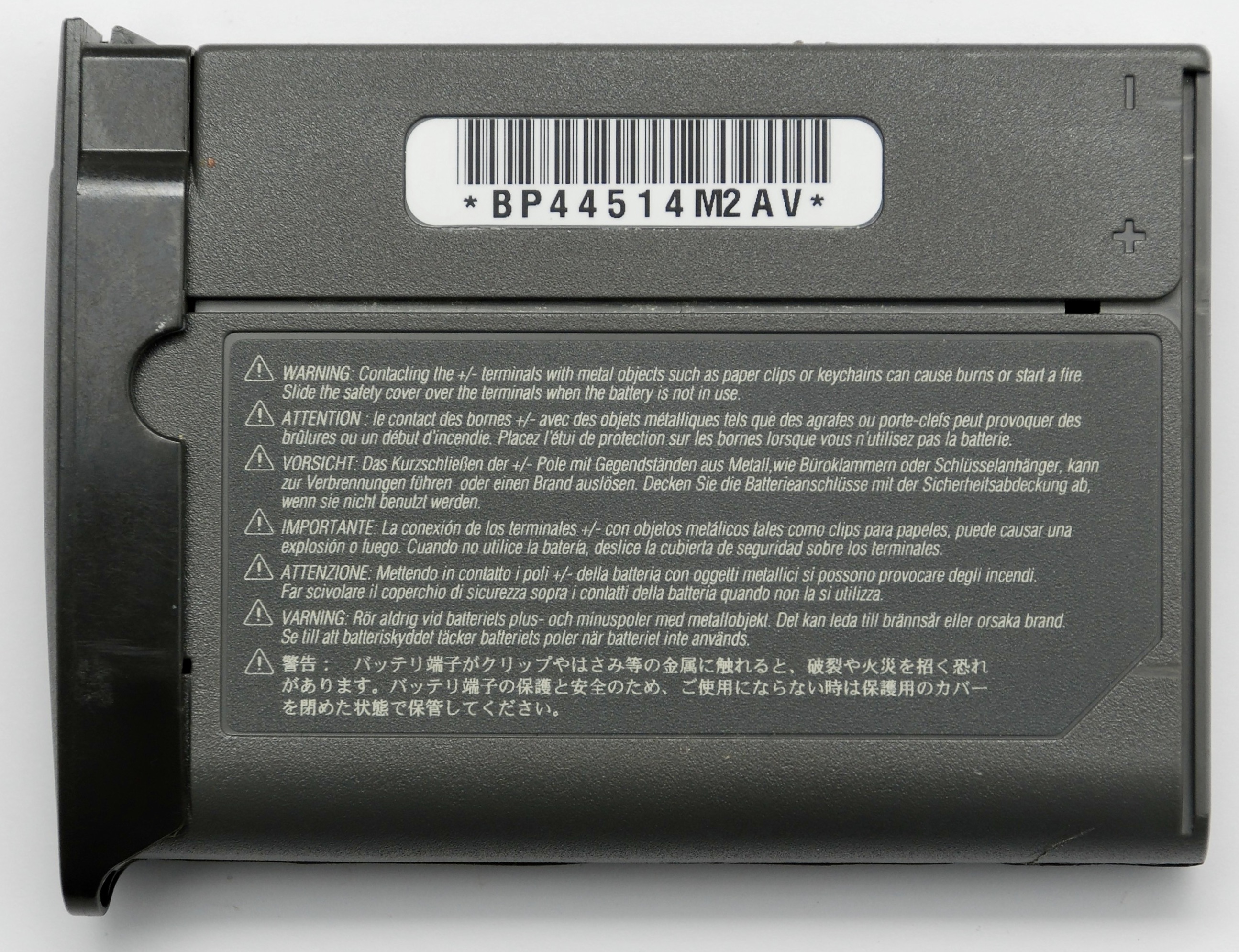
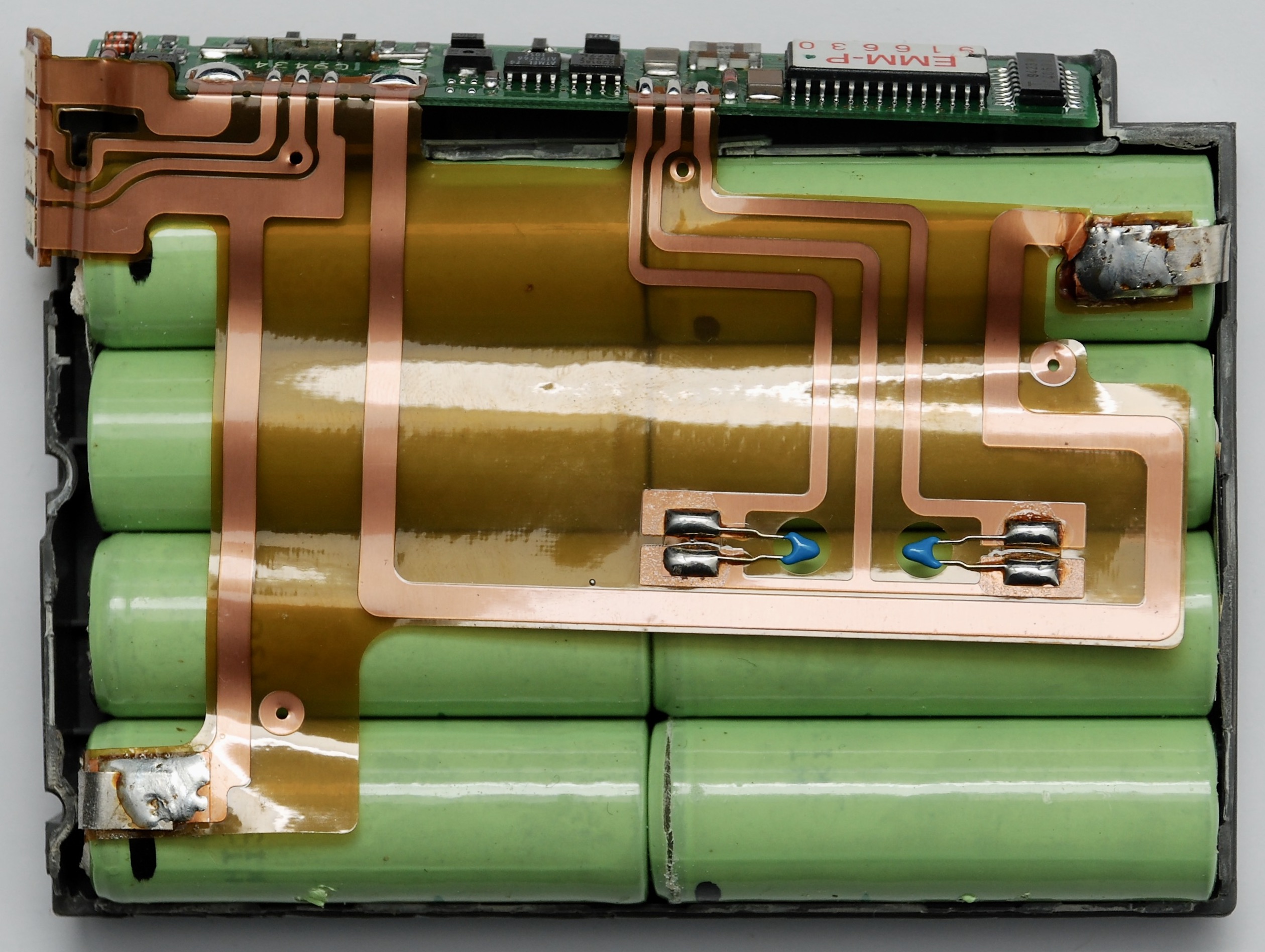
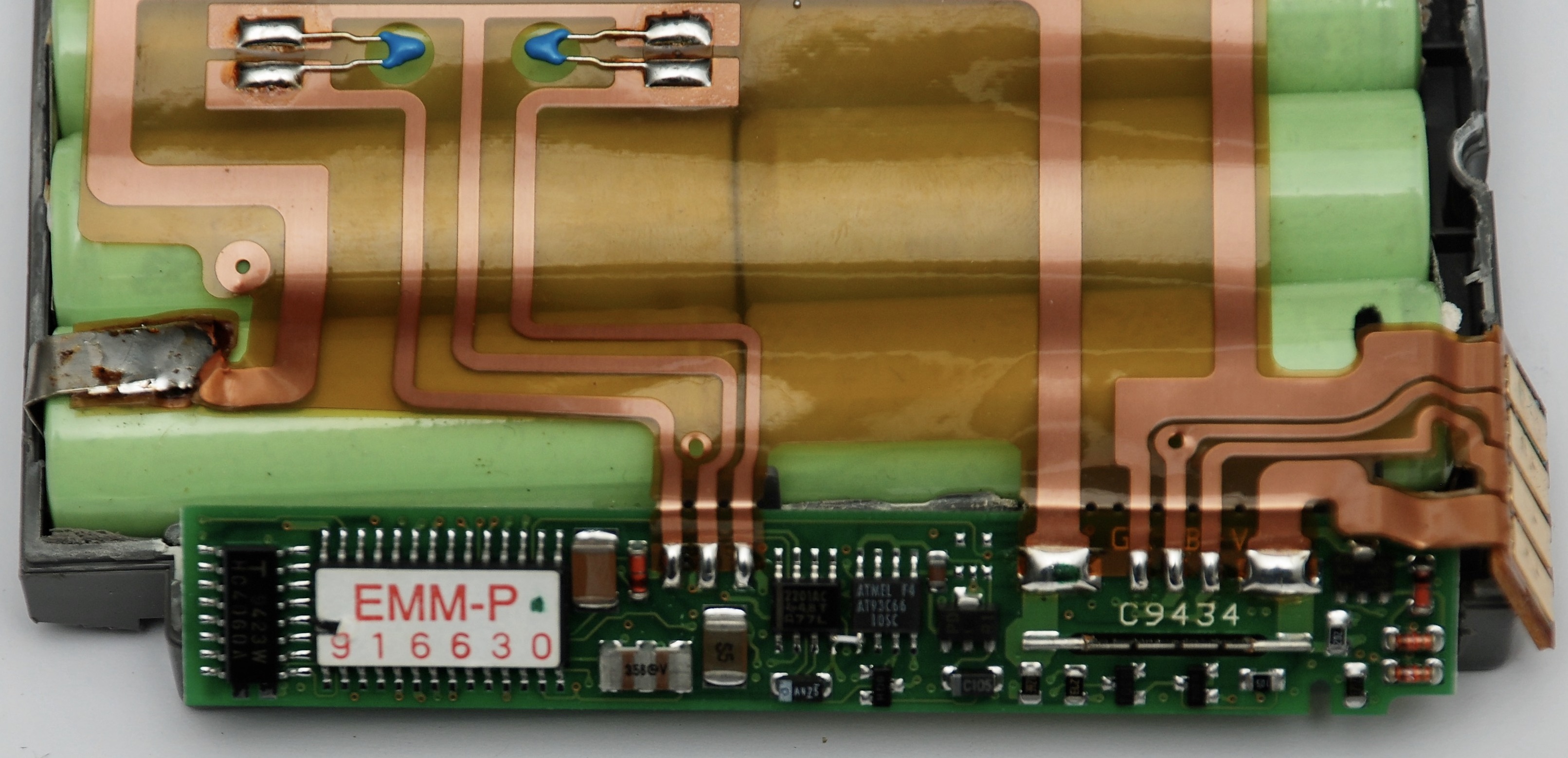
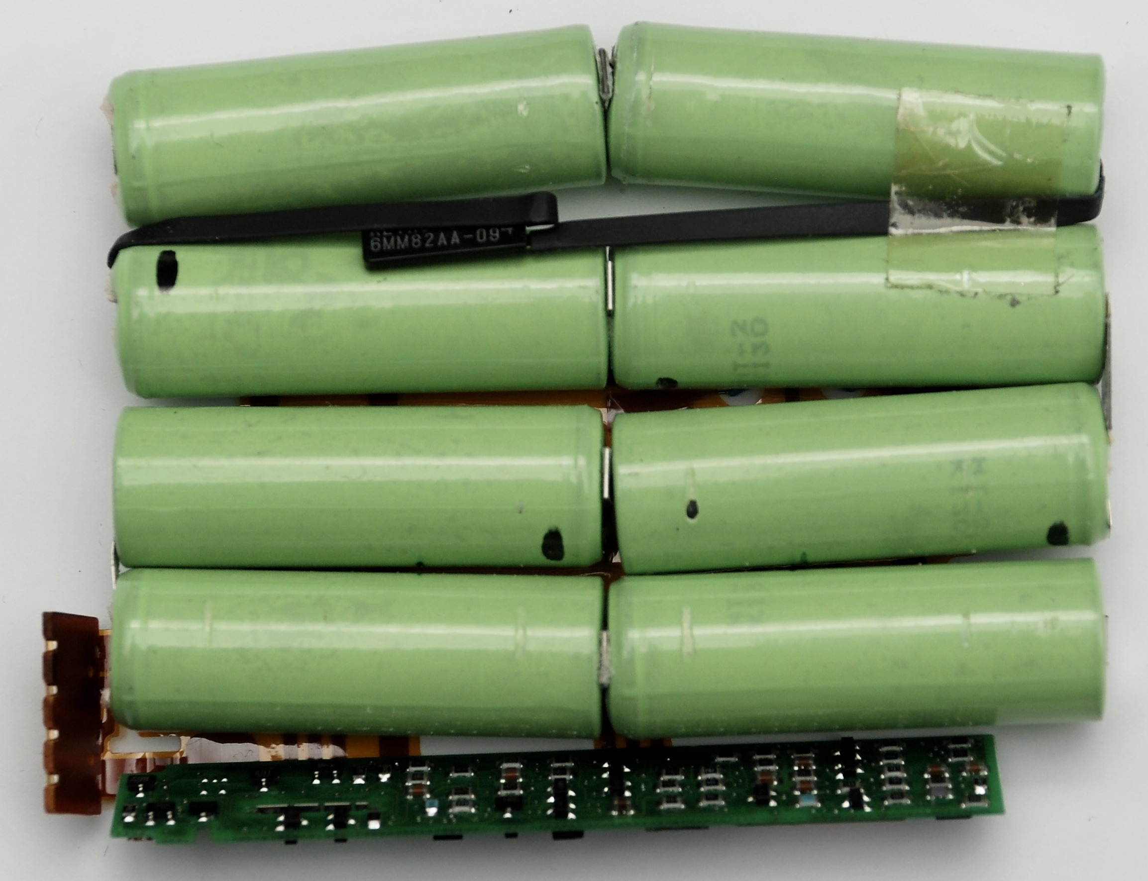
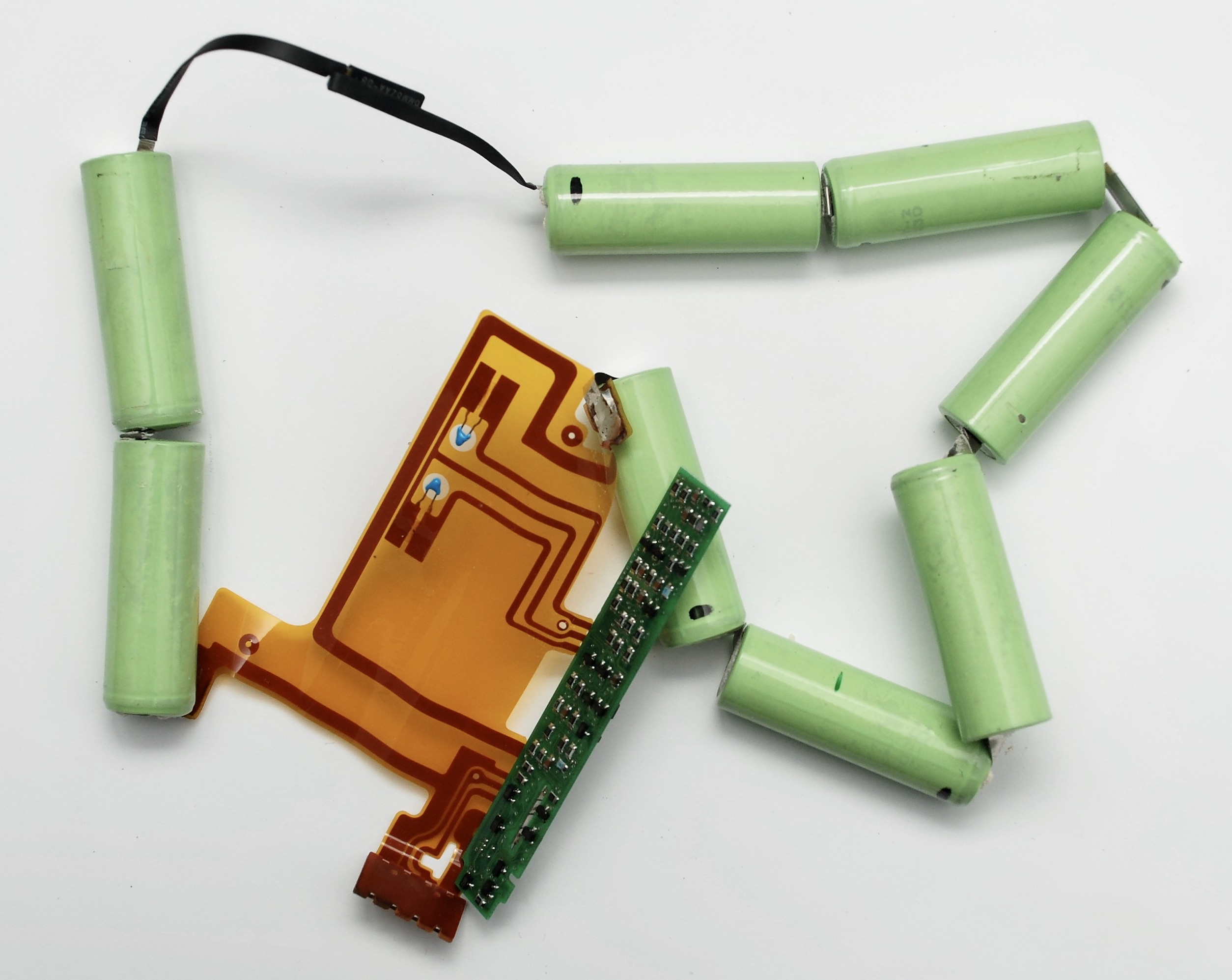
Battery

Reassembly

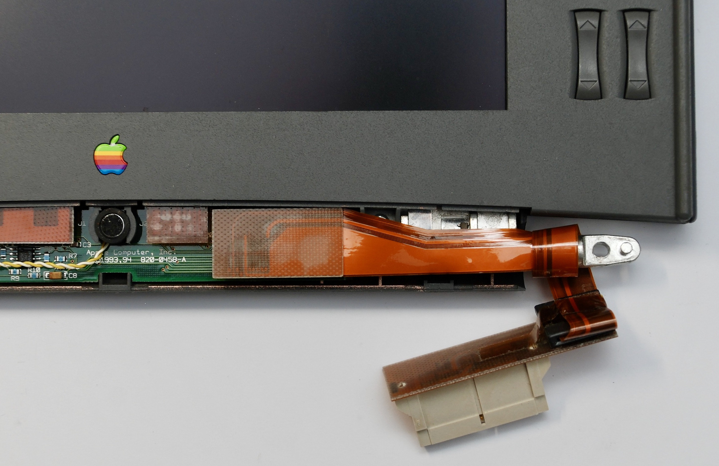


I place my bet on the 3rd tant cap from the left on the inverter board going pop first 🙂
Hi, Just wonder any reason for replacing those capacitors? and are they Electrolytic capacitors? It seems not. thank you in advance. MJ
They are electrolytic but in a plastic housing. The direct reason is the screen does not work as they leak and/dry with age.
ok well noted.. thank you again
Hi,
Any reason for replacing those capacitors? and are they electrolytic capacitors? it seems not. thank you in advance. MJ
Hi, what are the specifications for the capacitors you replaced on the display? Looking to do the same with mine, thanks.
3.3uF 35V, they are visible on the pictures
Thanks for the reply, I’ve taken apart my 520’s screen and I’m now wondering how am I supposed to recap with the plastic housing so close to the capacitor terminals? Is there a way to further disassemble the display without damage?
That is a great point. I don’t remember if the white cover can be dismantled further without a risk. It is quite possible I cut them out of the board and soldering new ones might have been easier, because I soldered tantalum ones that have pins and there is fair access to solder them without removing the white cover.
What tools or methods do you recommend for cutting out capacitors like that? I’m kinda new to board level repair.
I just finished the recap, however, there are still lines on the lower half of my display. Any idea what could be causing that?
Most likely this is caused by broken chips or connections to these chips that drive these lines. They are around the display under the white cover. You may try pushing gently the connections and see if it changes anything. If yes maybe installing some physical padding can cause the to stuck together. Otherwise it is rather irreparable in my opinion.
Please take a correction that I am a hobbyist practitioner not a professional. I use small side cutter pliers and cut the capacitor in half, if it is somehow glued to the board, watching the soldered side and pushing it so the pcb copper is not torn down. If it is not glued, just try to cut the pins or bend it up and down so the pins break. Without the capacitor, it should be easy to desolder the remains.
I just noticed, one of the capacitors is 10uF 16V