


Resources
Wiki
Commodore Monitors by Model Number
Documents
Internals
Main Board


In order to recap the board I recommend to remove the flyback transformer so it does not get damaged in the process of turning the board from one side to the other.
Capacitors list for recapping (all boards):


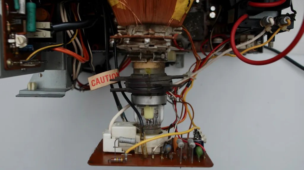
Flyback Transformer


CRT


Power Supply Transformer


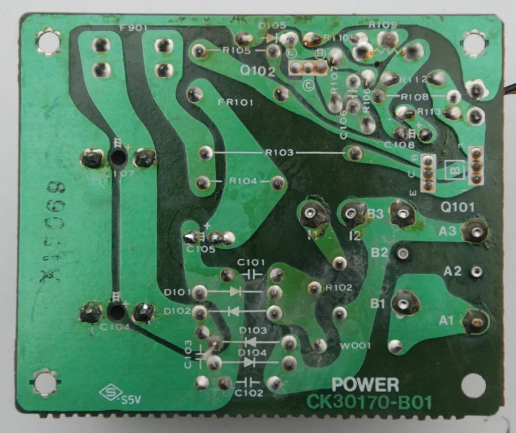
Power Supply Board


CRT Socket Board


Front Control Panel


The potentiometers on the front panel are particularly likely to wear out – the resistive path inside tears out and stops conducting. The results depend on the function – but if there is no reaction to turning the knob the first place to start is there. I did not find a way to fix them and did not find a replacement. The faulty one was for the colour and I soldered an internal potentiometer preset to a good value, but there is no way to tune it from the outside.
Rear Connection Panel


Voltage Selection Switch


Reassembly


Some Dirt (and Cables)


i am just recapping a PAL 1701 by myself and am a little confused about c201. This capactor seemed to be placed in wrong direction since factory on my board. The minus mark on the capacitor was on oppiside direction than the mark on the board. But the montitor always worked fine, so i looked into the circuit diagram of this monitor. if i understand it right, the + side of the cap is wired directly with r106 in this circuit diagram. if this is correct, the marks on the board are wrong and my capacitor was soldered in the correct direction although the board says it should be other direction. Then i compared it with the pictures on this website. The cap on these pictrues is soldered the other direction than it was and is on my board. it is soldered as the marks on the board are set. This contradicts the circuit diagram. i am wondering now, if it does matter or if it doesnt matter at all??? does the monitor on this still work with this cap soldered the other direction than on my board?
ahh after sending the comment i just saw, that there are more pictures of the board with this cap on this page… please compare the first picture at the top of the page with the last pictures at the bottom of the page. You will see, that on the pictures on the bottom there is a cap 201 soldered in the other direction (as on my board).
Great catch, thanks for that. Commodore is known for wrong component marks on the boards (although this may be not original Commodore board, I don’t know). It looks like your board and the one on the bottom of the page are right – C201 should be soldered like there, even if against the marks. I must have made a mistake replacing this capacitor not noting the original position, but using what is noted on the board. The monitor seems to function correctly regardless of its position, or maybe I have not used the mode in which it matters yet. I need to look at the schematics to figure out what its role is. I will add a note to the page under the pictures about all of that.
Appreciate thiss blog post