


Resources
DDR Museum Exhibit
Robotron Museum
radiomuseum.org
Documents
Internals
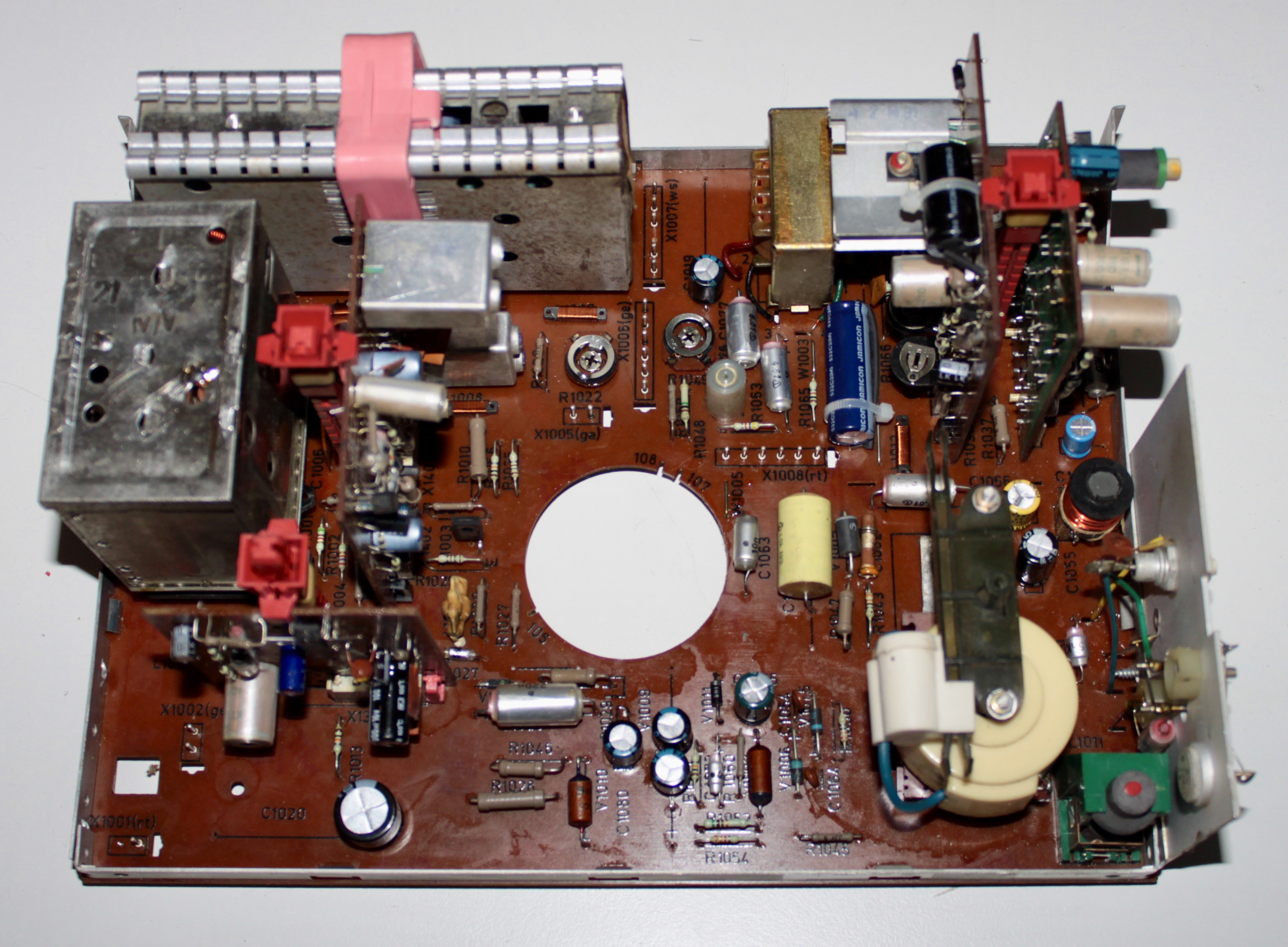
Main Board


The main board can have only vertical hold regulation or vertical and horizontal hold potentiometers. In case there is only vertical hold regulator, the vertical hold potentiometer is missing, its terminals are shorted on the board and on SG module pin 1 is connected to pin 3. Such board also does not have pin 3 installed on the SG slot.


Power Supply
This is a power supply from 1981:


This is a power supply from 1985:


Plug-in Modules
The photos of the modules are of the two manufactured versions: one from 1981 and another from 1985. Their design is no different between these years.
NF Module (X1301)
Probably this is a Negative Feedback audio power amplifier module.


SG Module (X1501)
Probably this is a Synchronisation Generator Module (Synchrogenerator Modul).


VAD Module (X1401)
Probably this is a Video-Audio Decoder module (Video-Audio-Decoder Modul).


VK Module (X1601)
Probably a Video Control Module (Video Kontrol Modul) – the three potentiometers are for regulating vertical linearity and size.


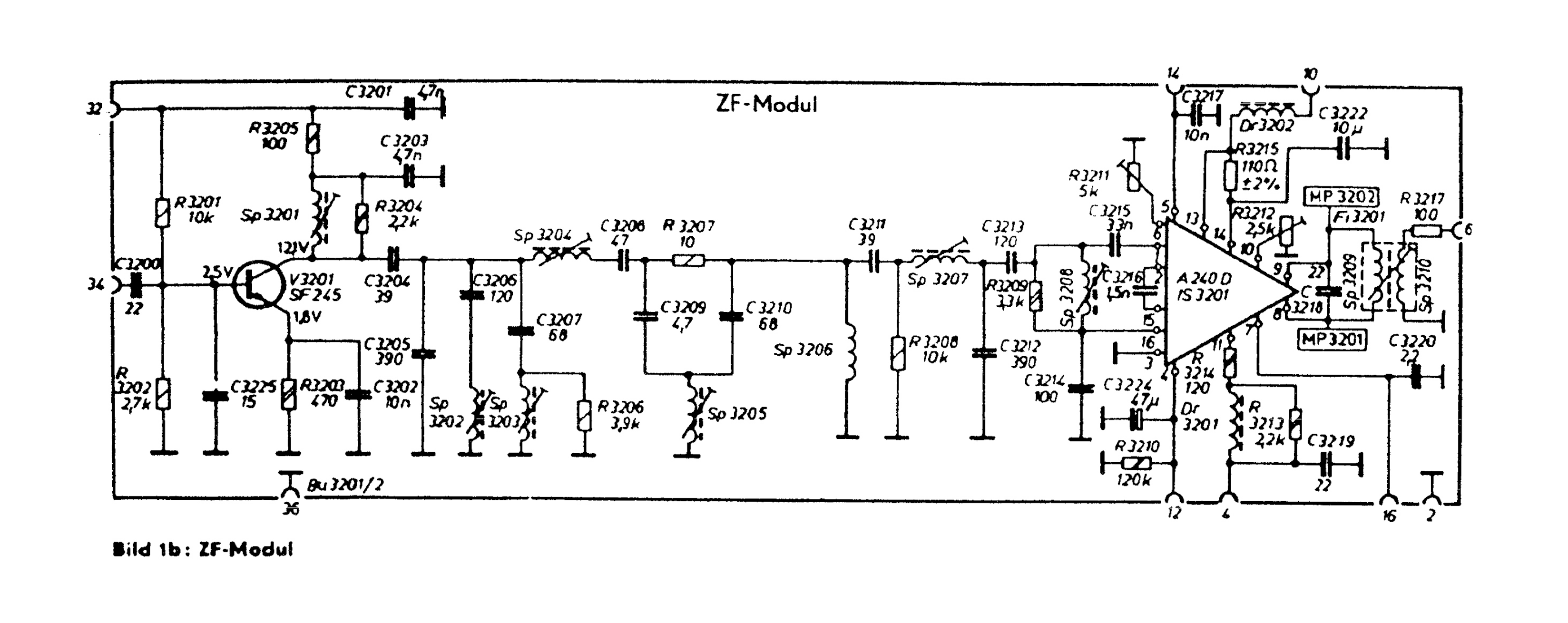
ZF Module
Intermediate Frequency Module (Zwischenfrequenz Modul)


RF Tuner Module


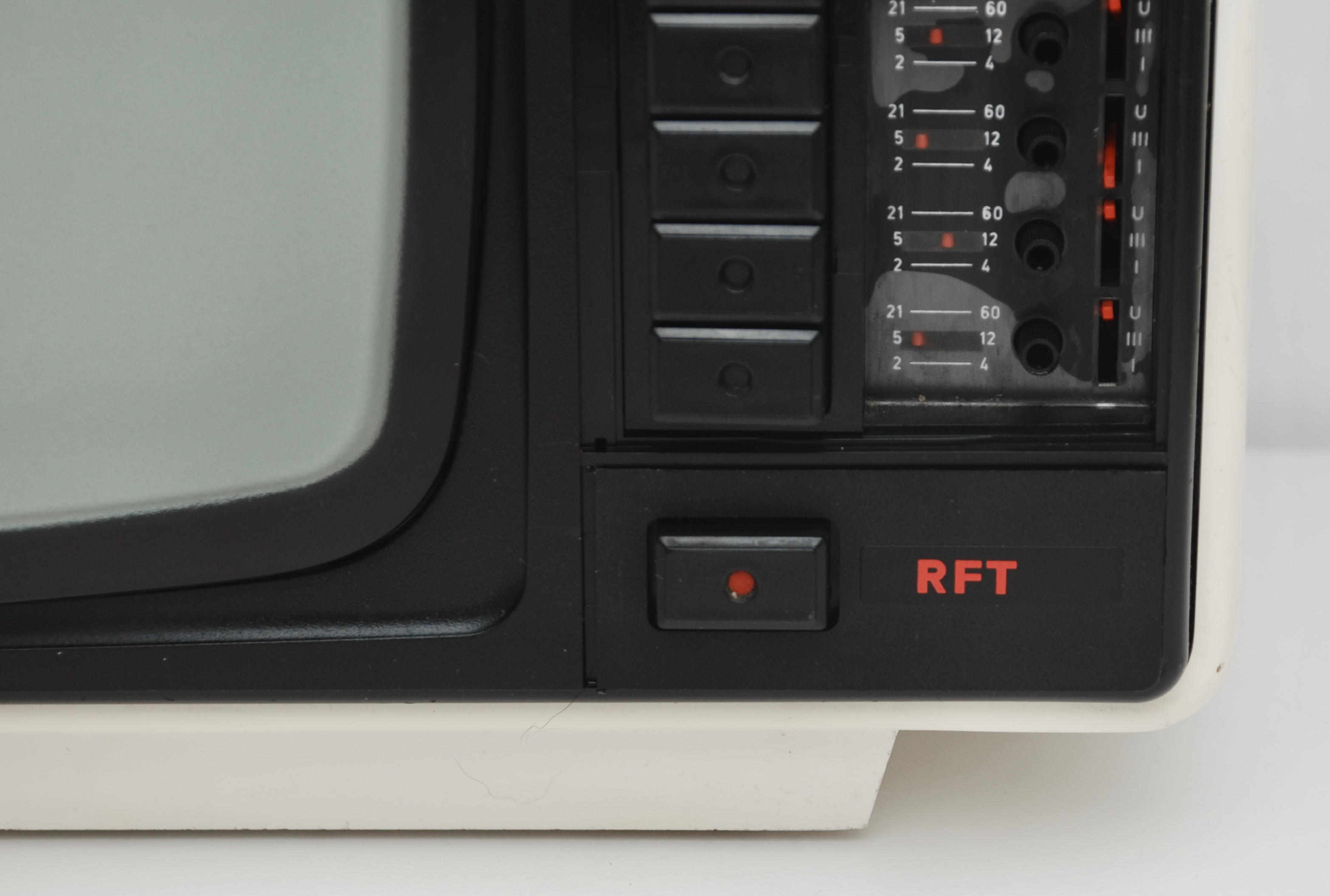
Tuning Panel


Volume/Brightness/Contrast Controls


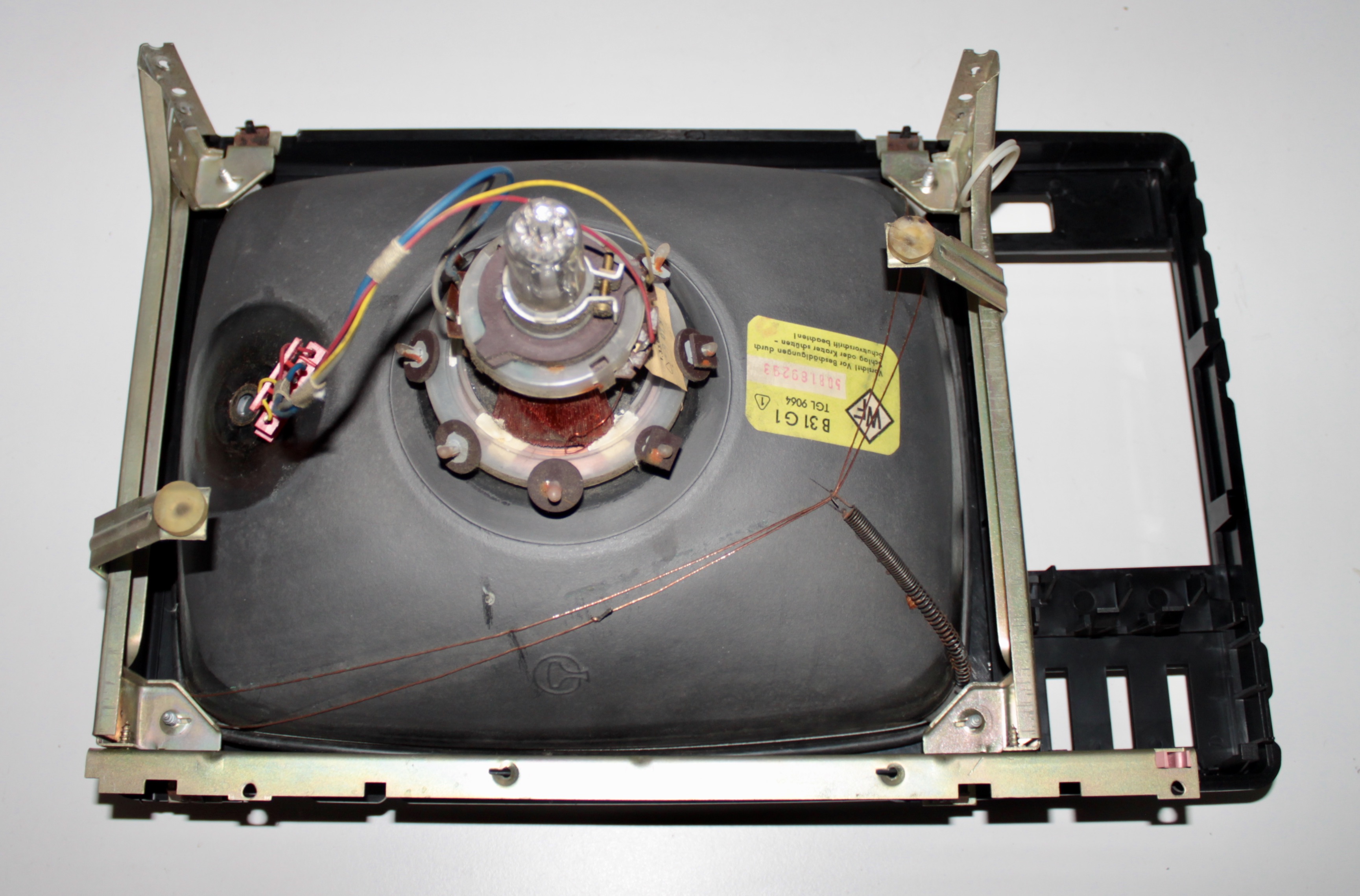
CRT
WF = Werk für Fernsehelektronik (TV electronics factory)


CRT Board


Some Capacitors


Composite Video Modification
My TV came with a mod that added composite video and audio inputs to it. The original mod looked pretty messy:


It adds 2xRCA inputs, a switch to choose between RF and AV and a potentiometer to regulate the input signal brightness. I took the modification apart and put it back:


Here is a reverse-engineered instruction how to make the modification:

Reassembly