


Resources
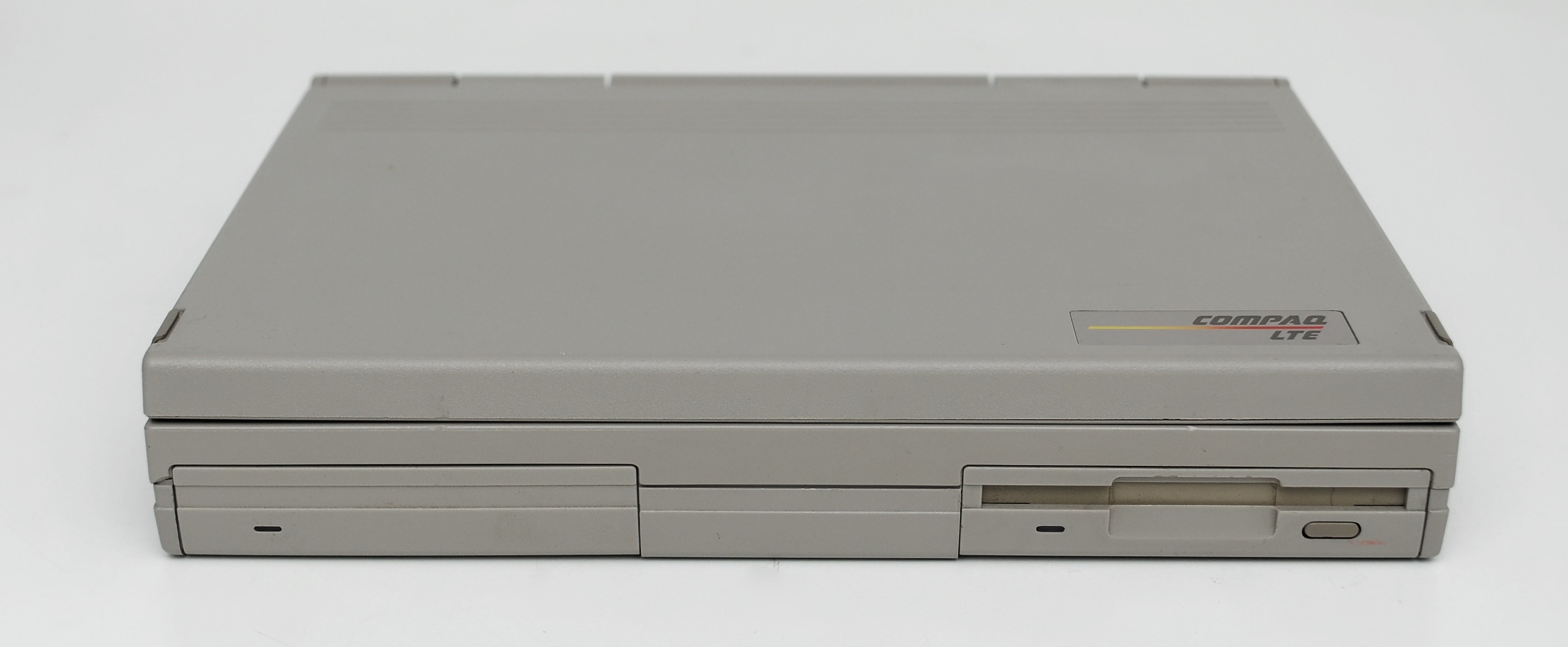
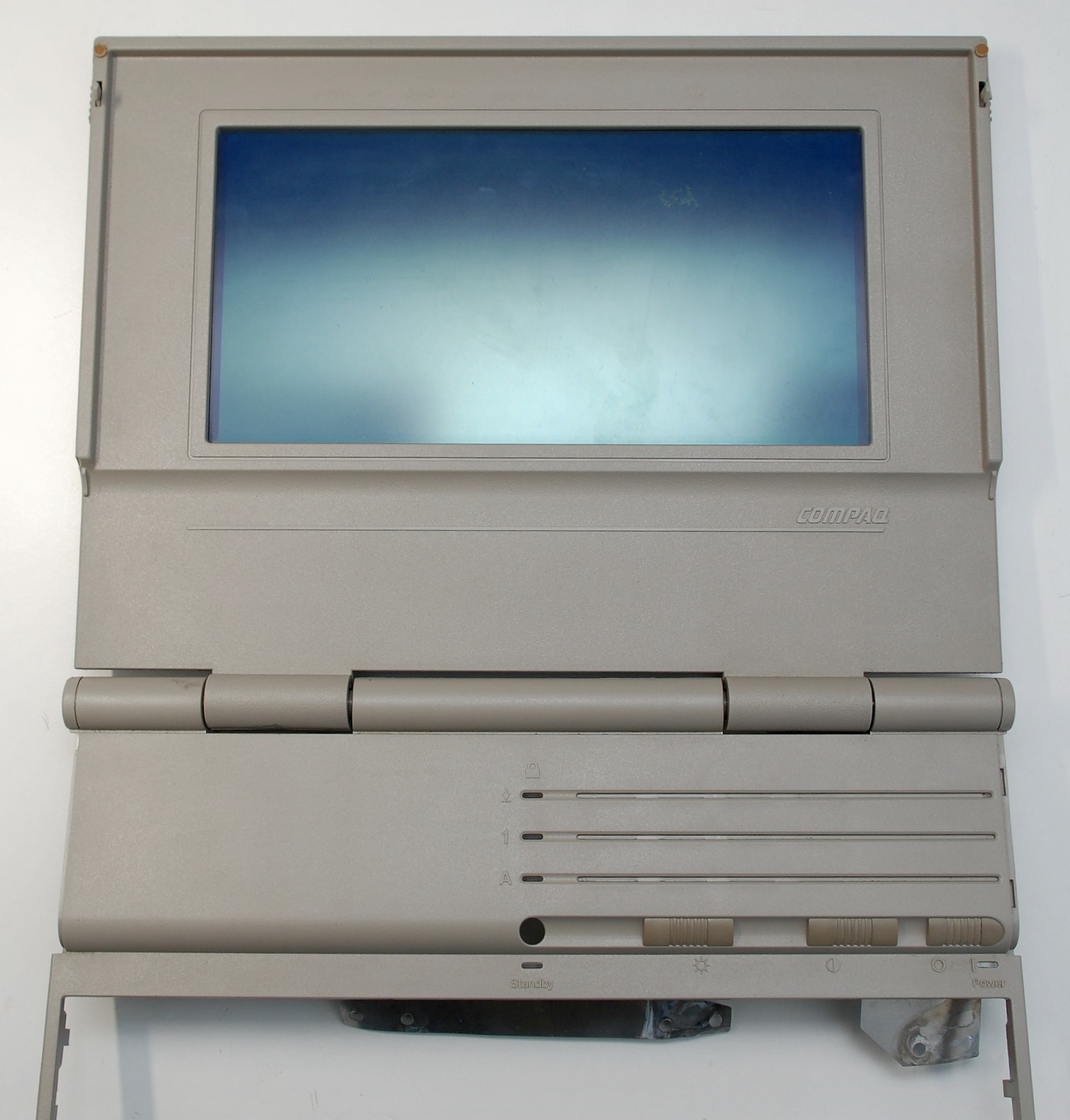
This machine looks as LTE/286, but it actually has 8086 processor and LTE marking on the cover.
Documents
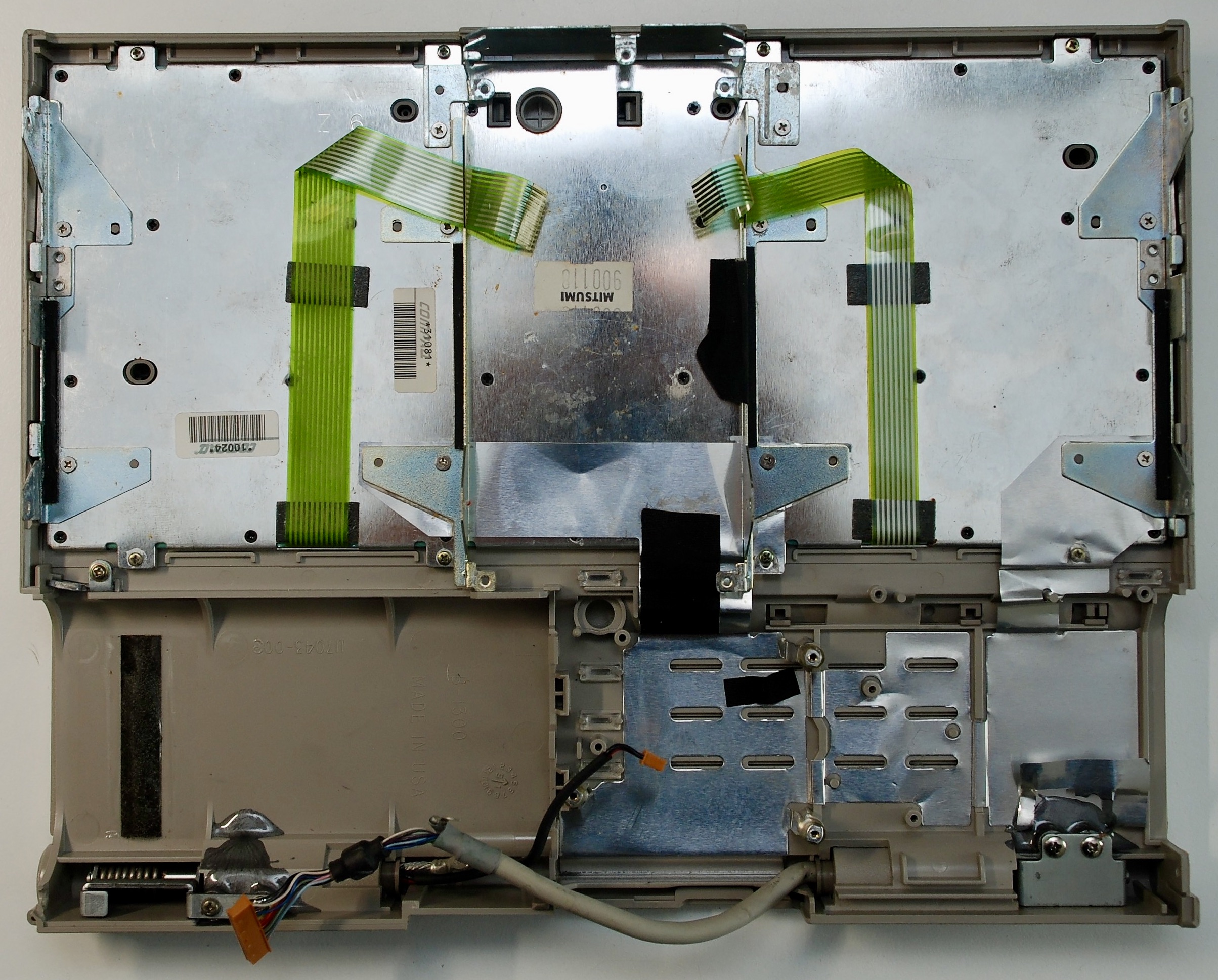
Internals
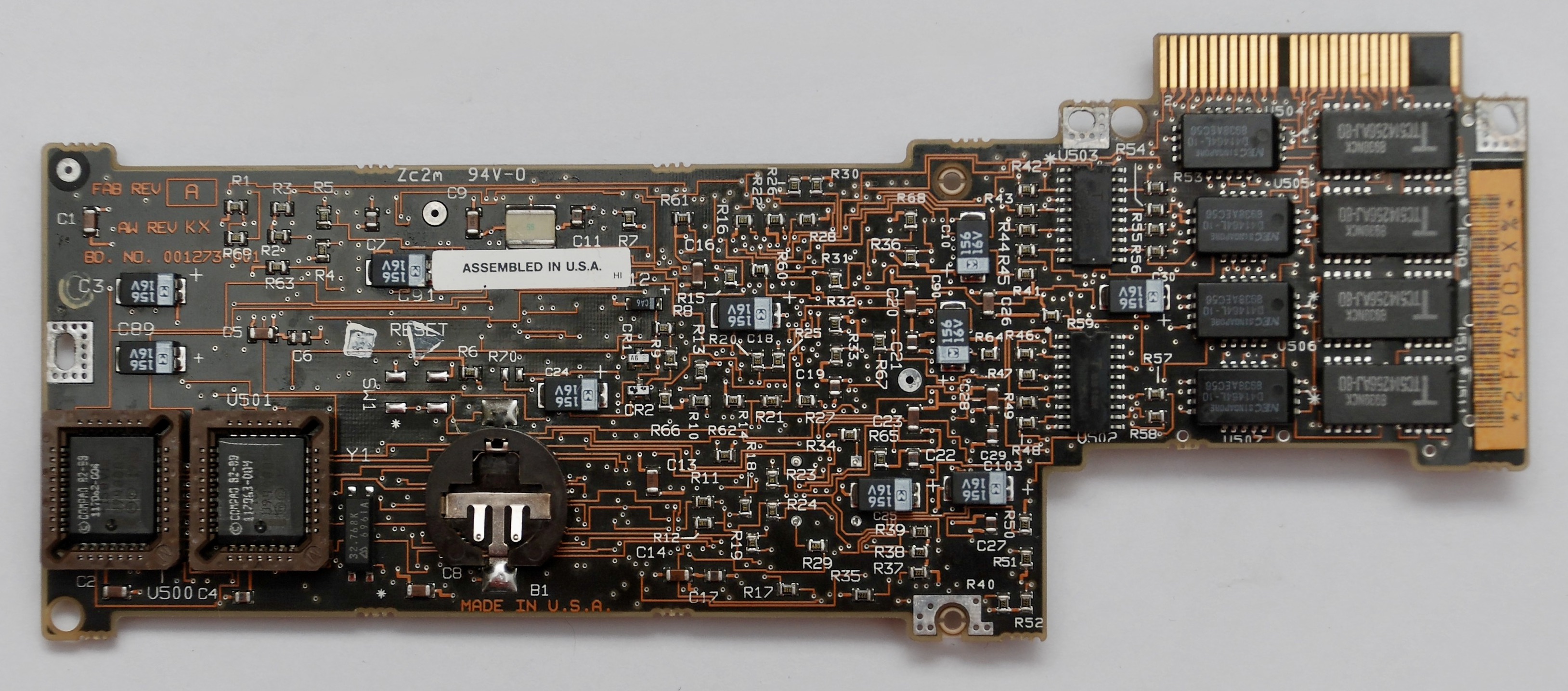
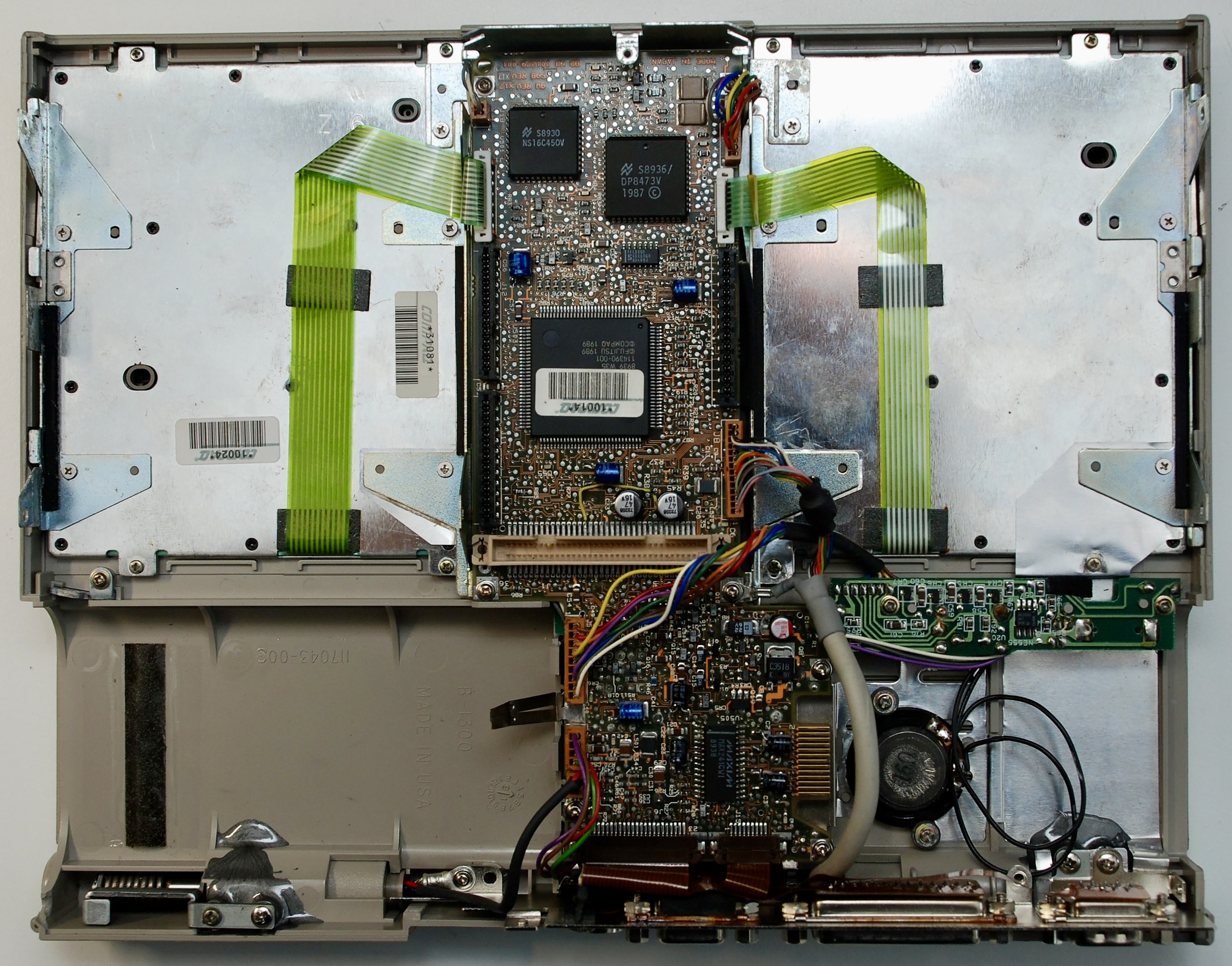
Motherboard

All electrolytic capacitors need replacement, they leak and destroy the board traces.
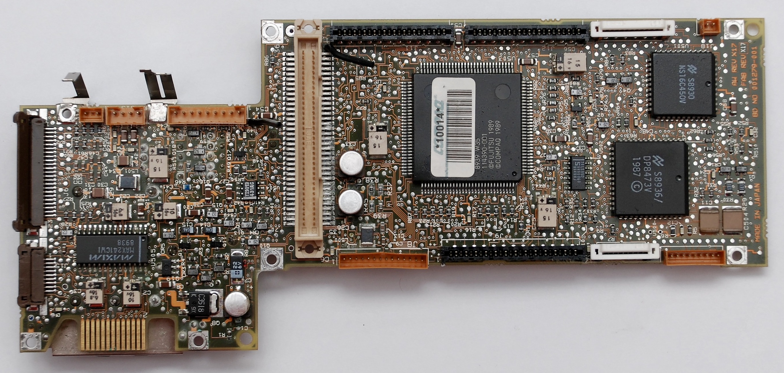
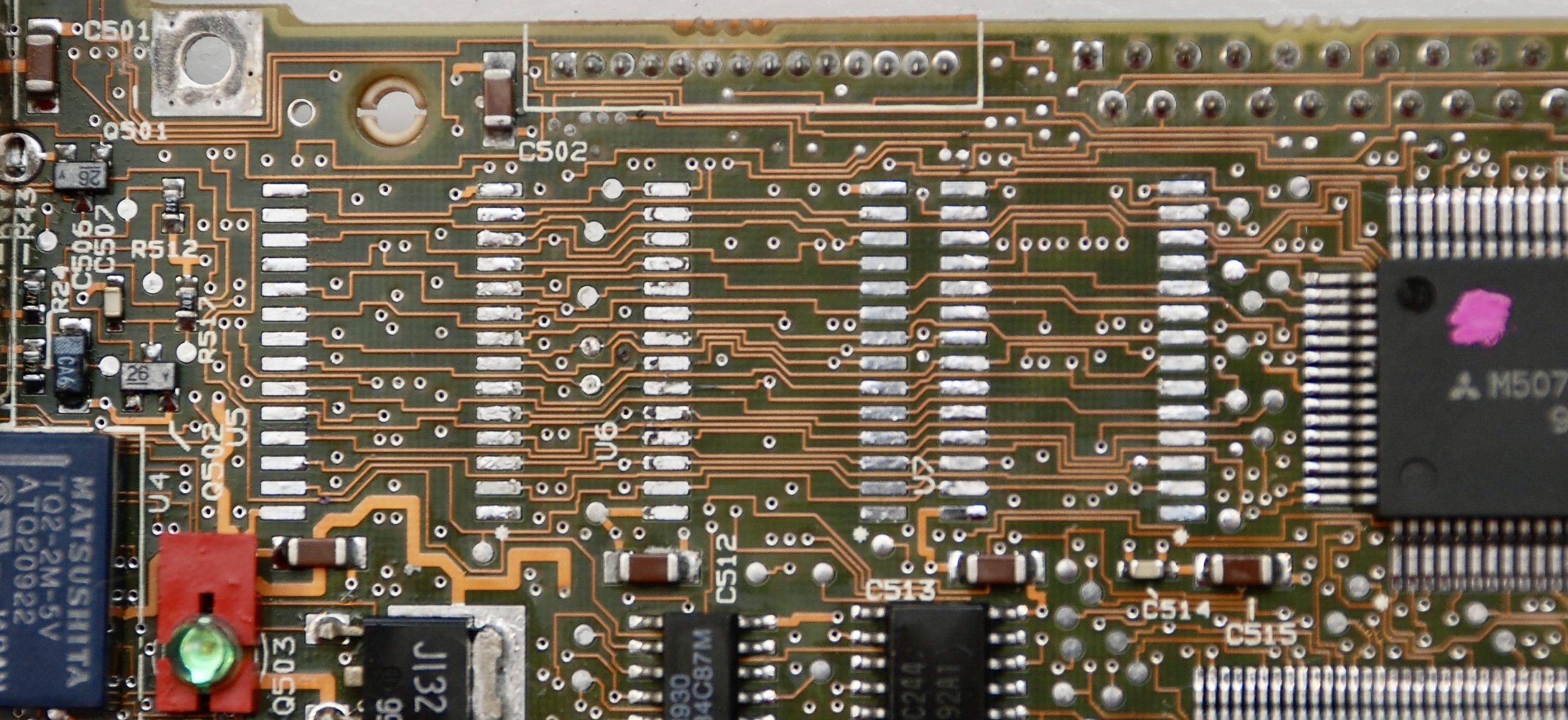
Daughtercard

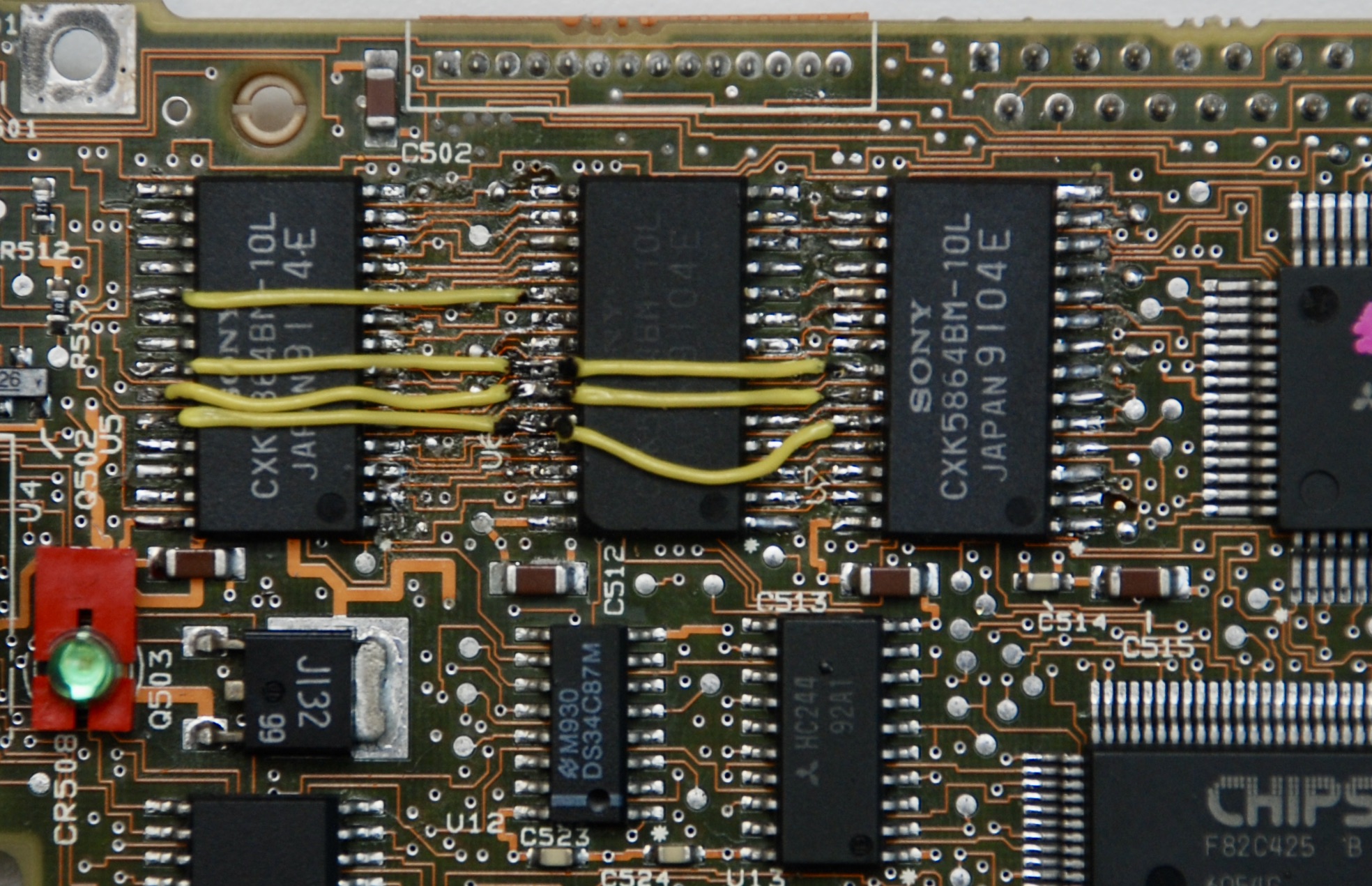
The three CXK5864BM-10L chips are SRAM memory used for video data. When they are damaged, there will be garbage on the screen, but generally, the machine will run. On my board the chips and traces below were damaged, probably from the capacitor acid. I removed them to uncover the traces and learn what the correct connection should be.
Then I soldered them back and fixed the broken traces. It does not look super nice, but works.
Floppy Disk Drive
Citizen U0DA-02A


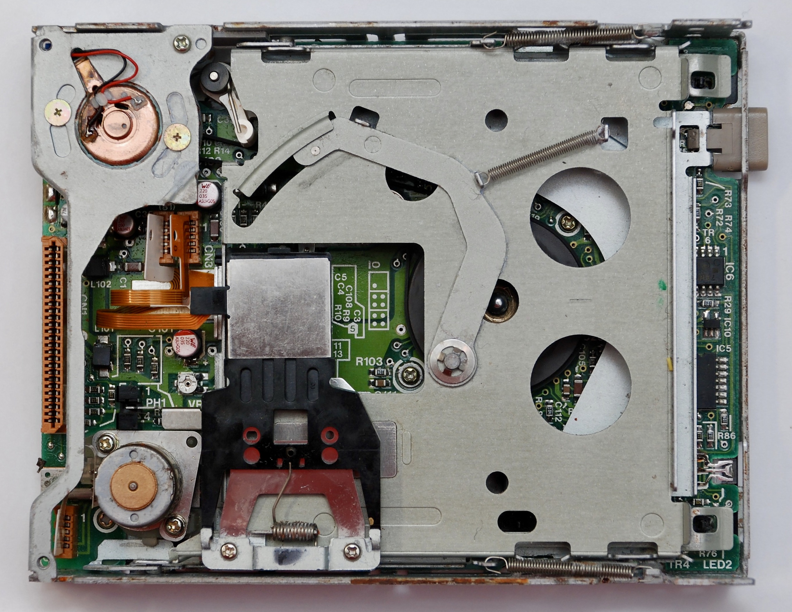
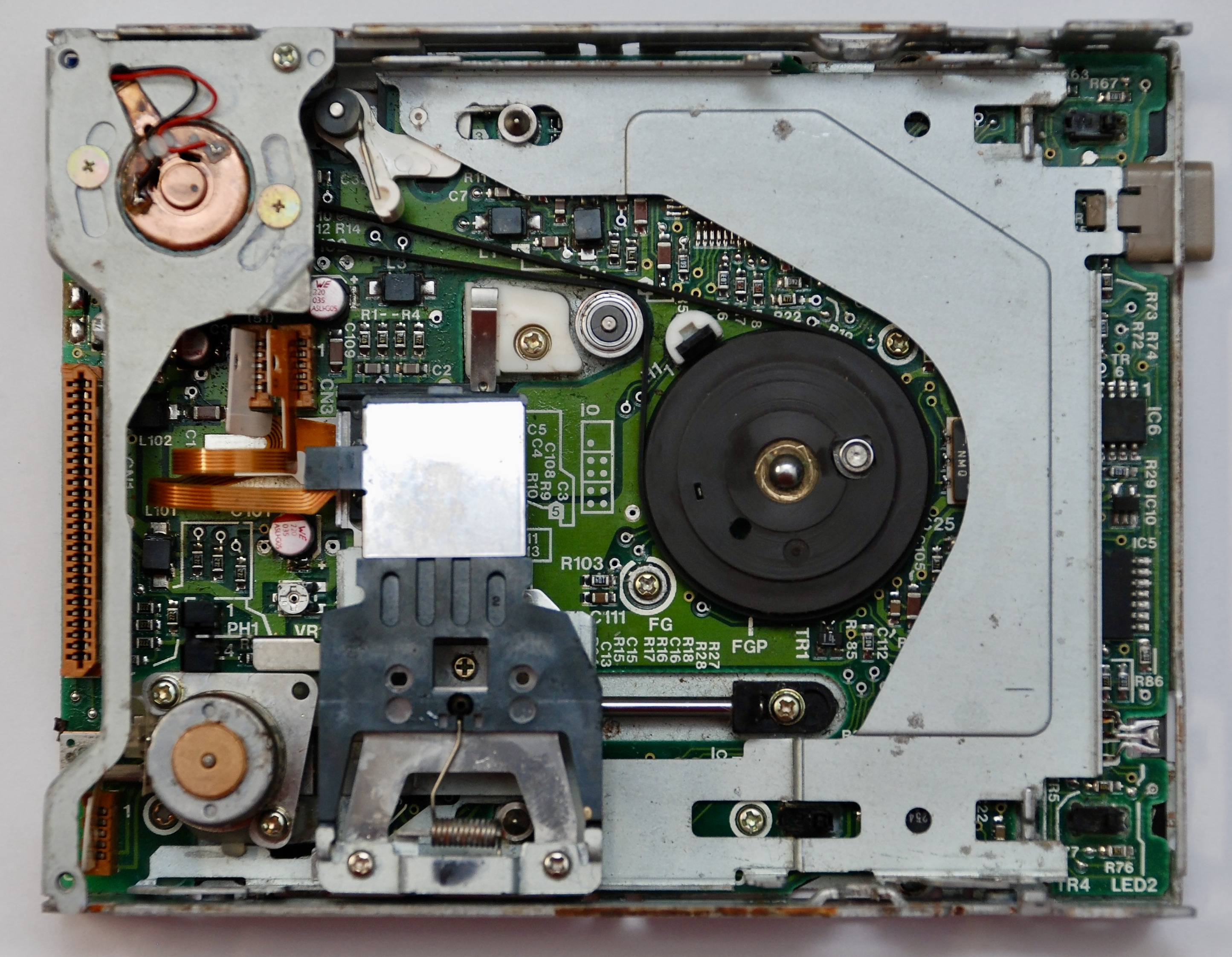
There is a rubber belt propelling the floppy, it most likely needs replacement. I just used some other belt I had that fit, but I don’t know the parameters of the correct belt.
Hard Disk Drive
Conner CP4021


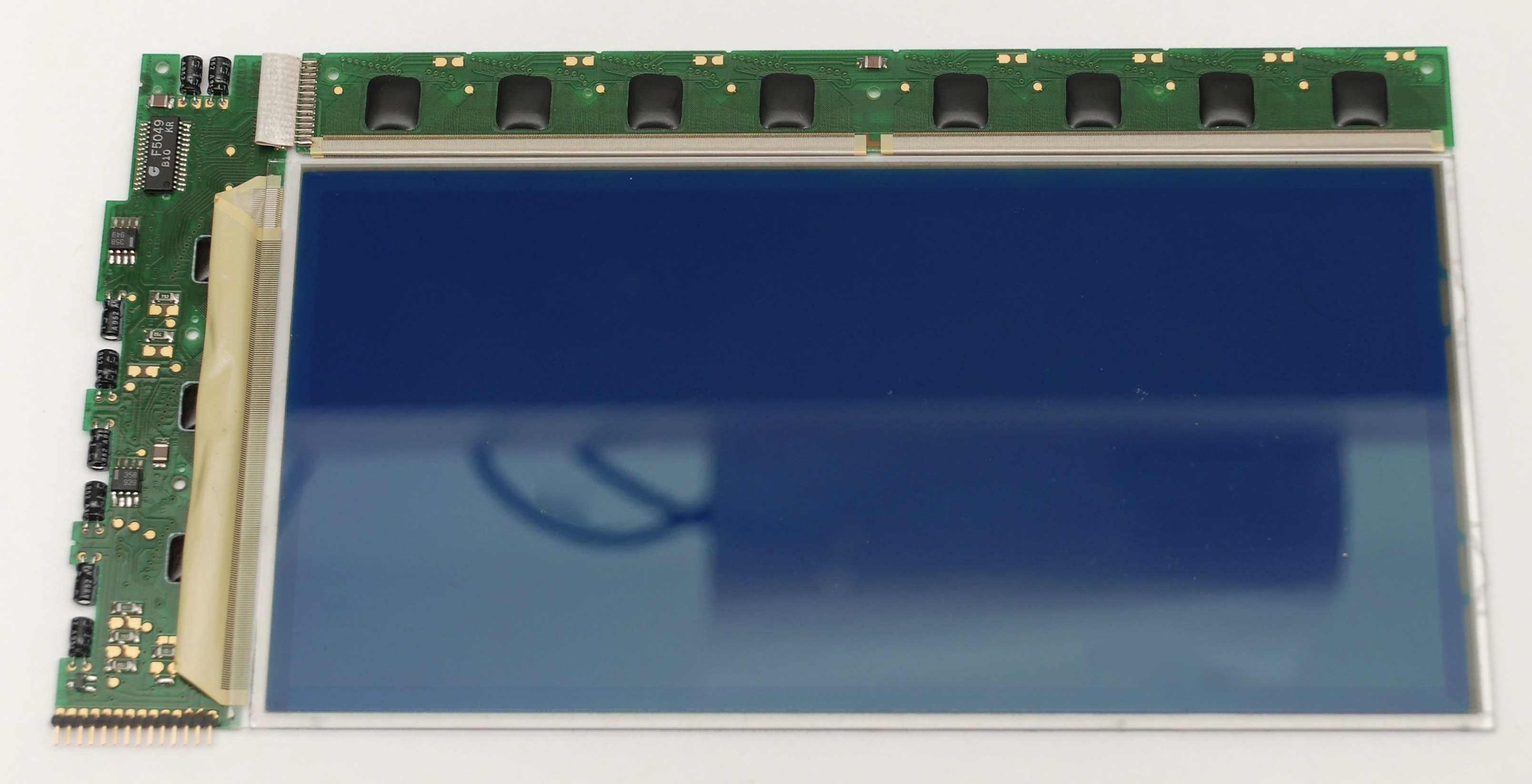
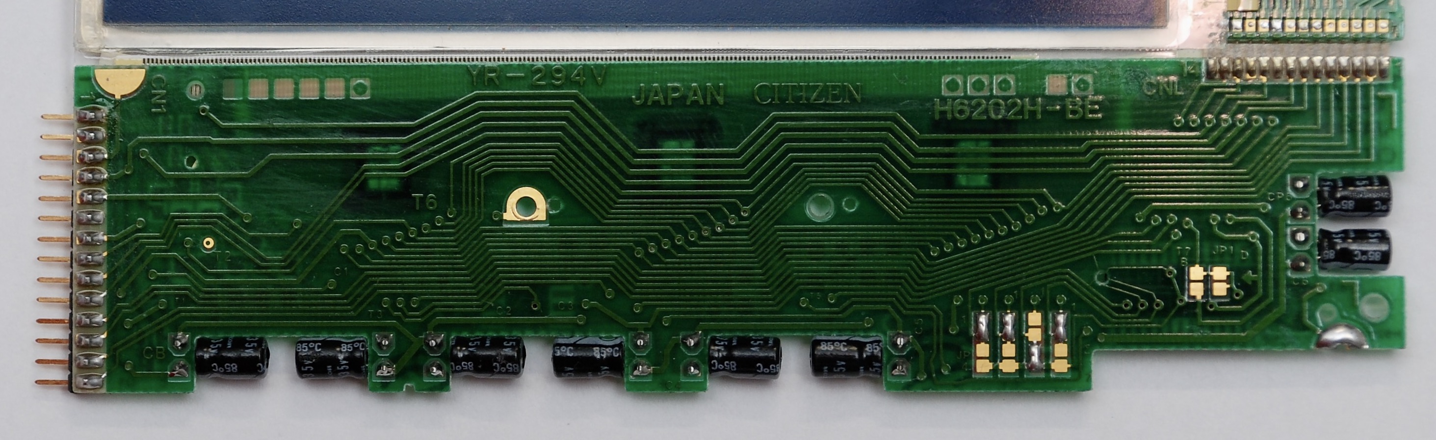
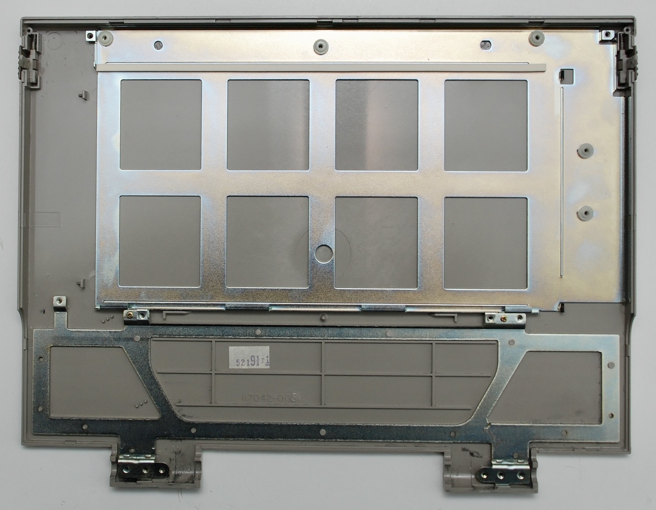
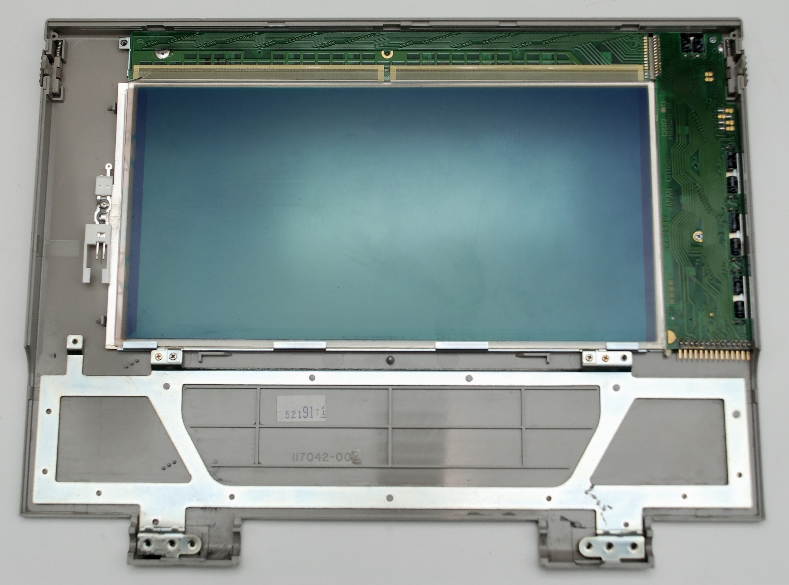
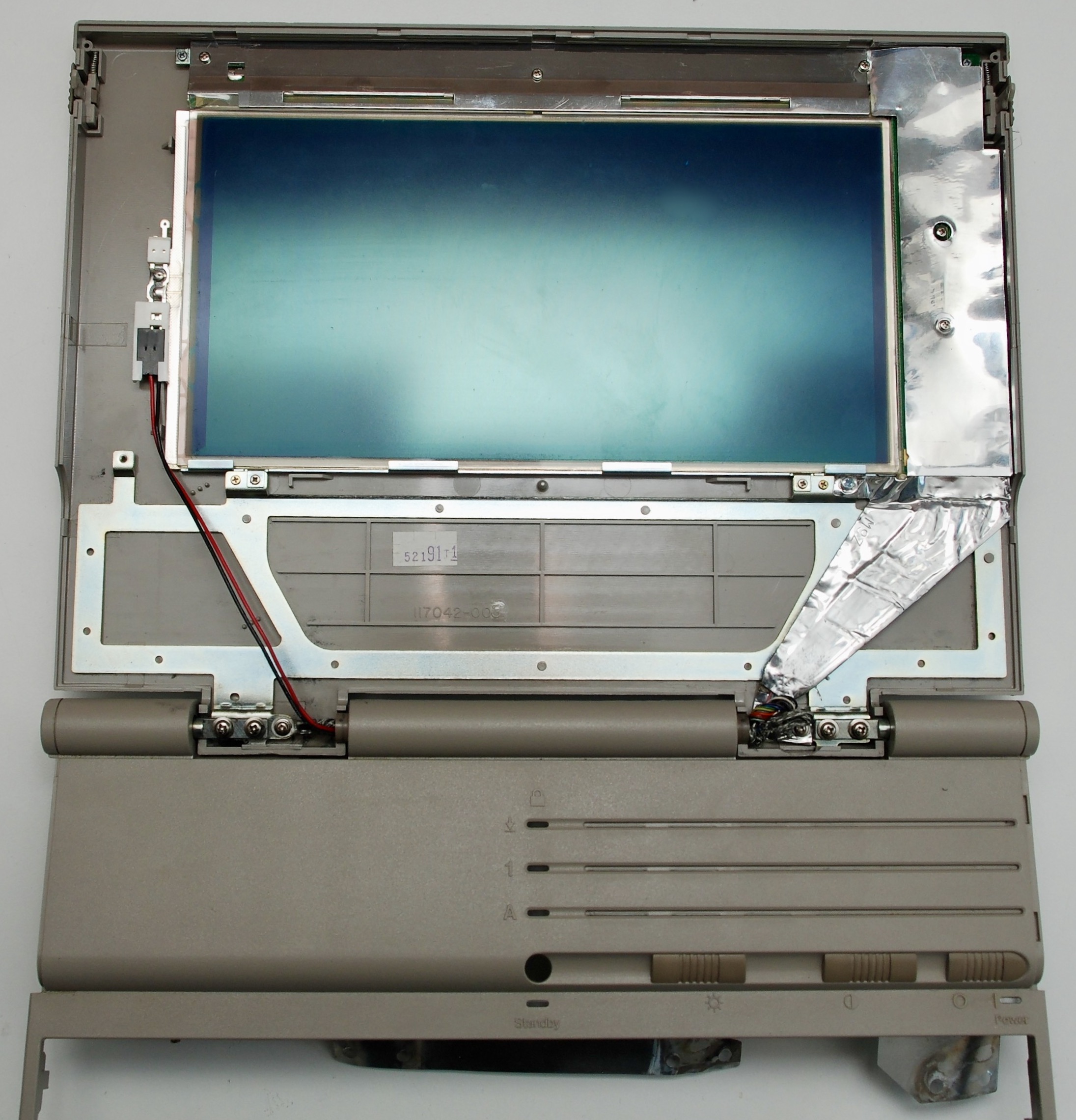
Display and Backlight


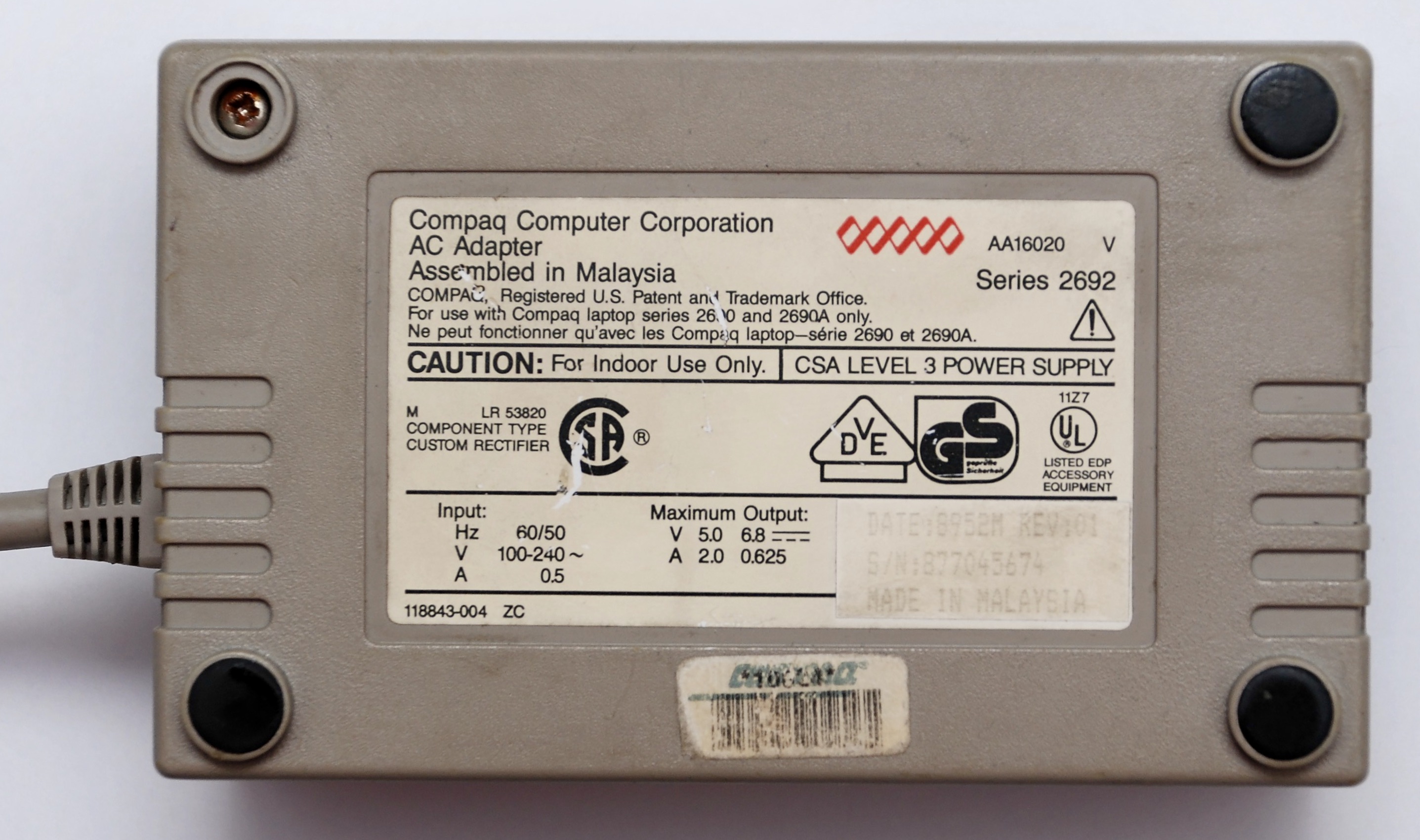
Power Supply


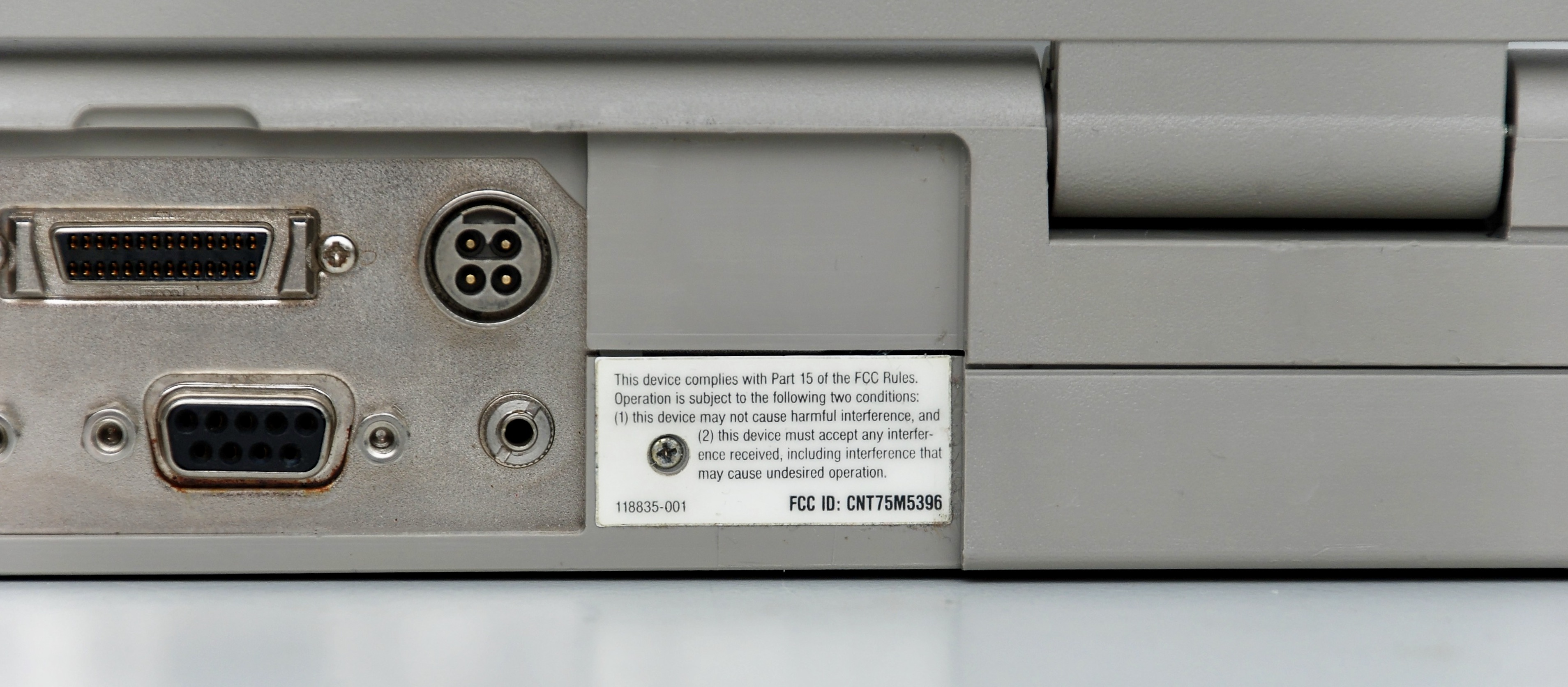
Connector panel


Keyboard
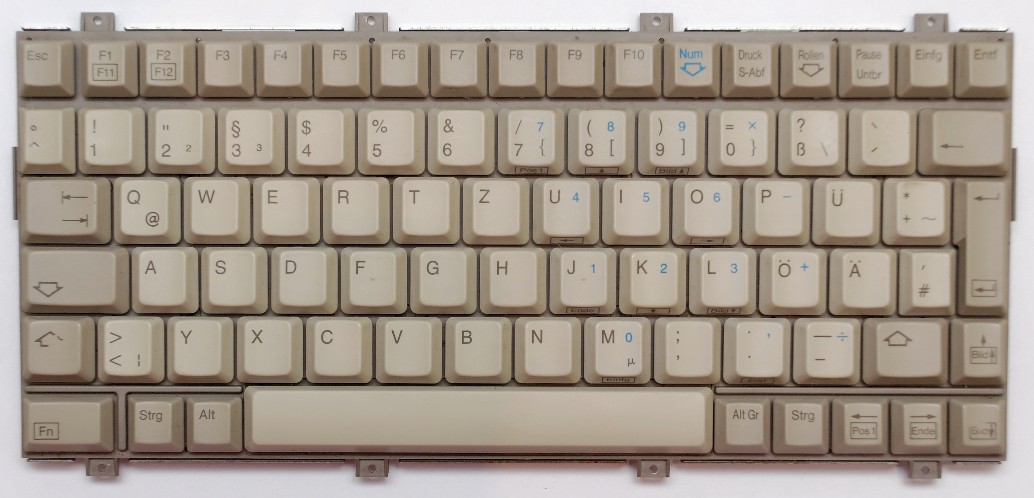
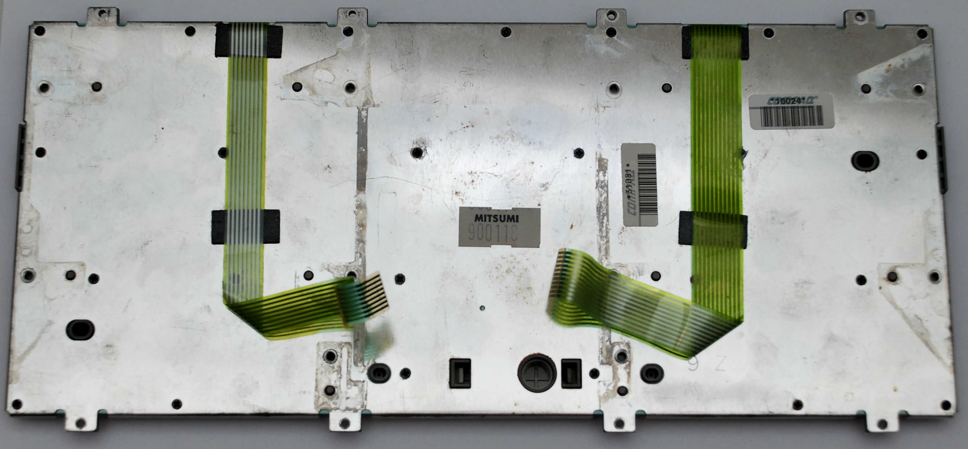
The connecting surface at the end of the tapes is likely to wear out or break resulting in sections of keys not functioning. A way to fix it is to cut the tape end off completely (the black carbon part) and to scrub the insulation from the silver traces creating a new connector. Then insert it together with the plastic tab that was on the original end. This will work, but probably it will easily break if there is need to remove and reinsert the connector multiple times to the motherboard.
Bag


Reassembly


That’s the first compaq notebook from 1989 and runs at 10Mhz. For something that is over 30 years old and with all those SMD chips and components, just shows that Compaq made high quality machines. Pity about all those SMD caps which certainly must be replaced!
Another great post!
Potrzebuję zasilacza do tego laptopa.
Hello
Thanks a lot for this great post.
I am currently in the process of repairing a LTE 286 and the damage is almost catastrophic: Stuck HDD bearing, stuck HDD arm, broken floppy belt, misaligned floppy head (after replacing the belt), faults (due to corrosion): no working backlight, no power switch, malfunctioning keyboard controller, broken memory traces on the GPU, and at least 10 more dissolved tracks that I had to replace with patch wires.
So far I could fix almost all of the issues (which took an insane amount of time) but there is one issue I am really really struggling with. The machine reports a “610 – External storage module failure” most of the time after powerup. In roughly 1 out of 10 tries the machine succeeds and boot without any issue.
According to the manual the 610 message appears if the external storage module is connected but not powered up.
So my theory is: The “external drive present” signal is corroded as well and therefore has some undefined voltage which sometimes is interpreted as 0 and sometimes as 1. The issue is, since the track is corroded, I cannot trace where the signal goes. I brushed the whole board with a copper brush that was connected to a continuity tester but had no luck whatsoever. Externally applying voltage to the pin also did not change the behavior (when powered up, the voltage is undefined and the connector pin seems to be high-Z).
Logically deducing to where the signal should go is also tricky. The other signals of the external storage connector end up all over the place. Most are connected to the floppy controller IC, some to the large ASIC, others to a differential driver IC…
Honestly, I feel a bit lost without knowing where the signal is supposed to go. Do you have by any chance a board still lying around and would be willing to trace that signal for me? The connector pinout is described on the technical reference guide page 6-95 (but the documentation is lacking a lot. The image there shows the pinout of the cable, so one the computer the layout is mirrored. The pin numbering is 1-14 in top row and 15-28 in bottom row.
Thanks and best regards,
befi.