


Resources
Wiki
oldcomputers.net – setup disks
Documents
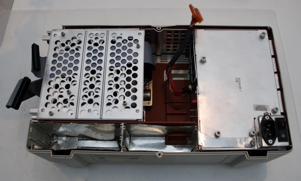
Internals
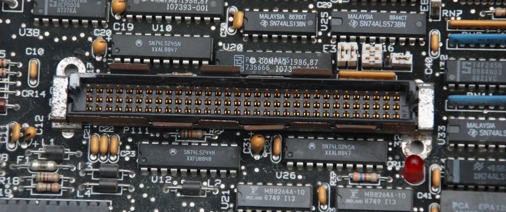
Motherboard


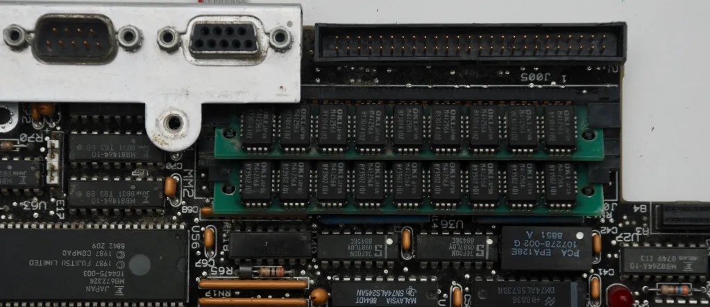


The computer will not access HDD when the CMOS battery is discharged or absent. There are two versions of the batteries possible:
- Integrated inside Dallas DS1287 real time clock controller chip. It is easy to replace the integrated battery with an external one, following these instructions. Please mind that my computer is missing the back cover, so maybe the battery needs to be positioned differently, but the idea is basically the same.


- Separately soldered to the board, with MC146818 chip instead of DS1287 – this version will have additional resistors, diodes and oscillator soldered near the chip and the battery. These components are missing in the Dallas version where some zero-ohm links are soldered instead.
Video Board


Floppy Disk Drive


Hard Disk Drive


Power Supply


Display
Panasonic MD400F640PD5 – gas plasma display.


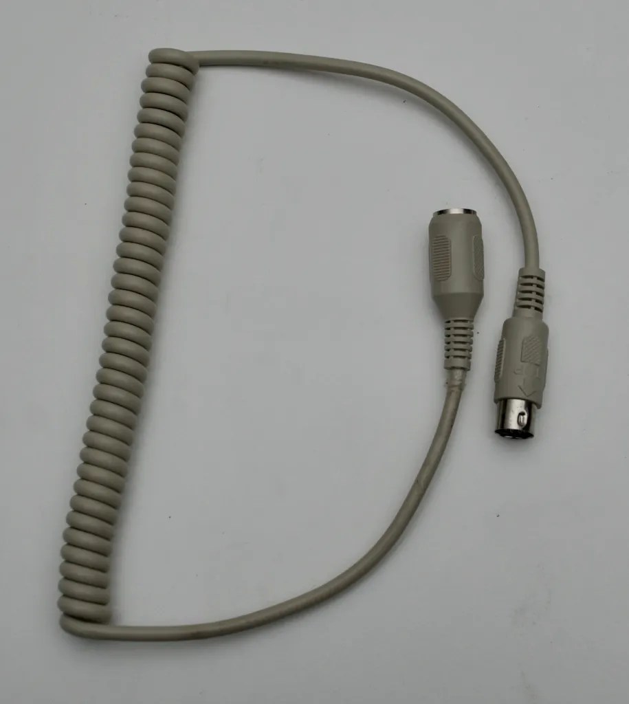
Keyboard
This is not the original keyboard coming with Portable III, but one taken from Compaq Portable 386. The keyboard seems to be compatible, also physically fits the cover perfectly.


Compaq Portable keyboards had cords in which the plastic cable coating broke easily with time and fell off leaving the bare cables visible. A vintage keyboard extender may be used as a replacement.

Reassembly


Other
Signal at pin 2 of the LCD screen 4-pin power connector

Hi, you can tell me the pinout scheme voltage of the 4-pin red molex connector that powers the LCD screen. Then the voltage is in DC or AC? please.
Yes I will take a look during the weekend as I am away from it now.
Thanks. The purpose is to replace the original power supply with a modified atx pc or a modular power supply.
Do you mean this connector: https://oldcraporg.files.wordpress.com/2018/11/dsc_0071-1.jpeg
It is not red in my machine, but this is the only one with four pins.
The voltages are:
pin 1: ground
pin 2: +5V (not clean signal, see the picture I added at the end of this post)
pin 3: -200V DC
pin 4: -200V DC
pin 3 and pin 4 are not the same, the resistance between them towards the motherboard is 600 ohm
thanks for your help. That white connector then connects to the red molex connector of the main power supply. Are the 200 dc volts negative?
Yes negative against pin 1
it will be difficult to find a power supply that does even -200volt dc together with +5 +12 -12.
Love the machine and this is some excellent documentation! I have a Portable III myself, and am in the middle of replacing the old frayed keyboard with a new cable. I made the mistake though of not documenting the pinout of the old cable, and every combination of wiring I can think to try from the new cable to the keyboard’s internal connector doesn’t seem to work when testing on the machine. Do you happen to know the pinout between the keyboard port on the machine to the keyboard’s internal connector? Thanks in advance!
I am sorry I missed your comment. I have not made any notes of how to connect the keyboard. Did you manage to solve it? I might open the keyboard and see, this should be easy.
Thanks for the reply and sorry this one is late as well! I have not yet solved my keyboard wiring. If you ever get the chance to open up yours and see the wiring that would help greatly!
Greetings, to late but i’ve seen your topic and i’ve just dismounted a portable III keyboard and made some measurement …
i’ve photos of motherboard with color wires and i’ve measured which wire goes where…
If you want i can give you if webmaster give you my mail adress
best regards.
That’s great, can you please drop me an email to contact@oldcrap.org? Thanks!
The display is gas-plasma technology, not LCD, that’s why it needs the -200V.
Thank you, I fixed the description.
Does anyone have the pinouts for the power supply connector to the motherboard? I have a dead computer, and trying to start by verifying if I have a bad power supply. Turning it on, the only thing I get is a click from the relay. Both with and without everything hooked up. Thanks
Hey Pawel, thanks for this trove of info! I’m missing all the screws holding the mainboard onto the chassis, but they don’t appear to be standard M3, and the service manual just says P/N 107386-001 but not what they actually are. Any idea on what thread pitch and size they are? Cheers!
No idea. How can I tell it looking at the screw?
Hi silvervest1
Just looking at a Compaq Portable 3 that I had in the loft.
Motherboard has been trashed by the leaking Lithium battery!
The screws I have removed appear to be ANC No 6 thread. 0.138″ od 32 tpi
Regards
Mike
Sorry…..I’ve given the case screw info!
The Motherboard screws are smaller : ANC 4 – 40 0.112″ 40 tpi
Regards
Mick
Hey Mick, that’s fantastic, thanks! I needed the case screws as well so that’s tops.
Are you able to measure their lengths as well? I’m guessing just based on the mounts that 1/4″ will be fine but nice to know!
Hi Silvervest1
Motherboard screws are 1/4 inch thread length with a T-10 star socket head and have a captive shake-proof washer.
The case screws are T-15 star socket head with a plain washer.
The two short ones for middle of the back are 1/2 inch long thread.
The four corner screws are 4 inch long shank with 3/4 inch of thread.
Regards
Mick
Sorry that was the case screws!
Motherboard screws appear to be 4-40 ANC
Regards
Mike
Hi,
I’ve recently acquired this type of old crap and for a while I was super happy. It didn’t last long as it did last for only 20 minutes and ever since I am the devastated. Seems like during a power cycle something died in the power supply because since then the plasma display won’t light up. ( The computer itself boots up, the logic power train is fortunately a totally separate circuit in the PSU ) I’ve disassembled it to almost atomic parts, took the capacitors out, checked every transistor I could find, and they seem to be fine.
I’ve took some measurements on the high voltage outputs, and I was shocked to find this:
pin 1: ground
pin x: n.c. ( an intentionally missing pin as protection against general stupidity )
pin 2: -120V
pin 3: -200V
pin 4: -195V
As this makes no sense whatsoever in respect to the measurements Pawel took ( except reading it backwards ), I assume I am now in need of a schematic or someone that is kind enough to help me and has access to a working Portable III.
Please help, or else… 🙂
My measurements were on the LCD connector, which connector did you measure?
Hi Pawel,
thanks for the fast response. I’ve also took my measurements on the display connector. The marking on the display PCB says:
1 – GND
2 – n.c.
3 – +HV ( positive high voltage from ground, should be +200V –> on the PSU PCB the wire is marked 200T )
4 – -LV ( negative logic voltage from ground, so this should be -5V )
5 – -HV ( negative high voltage from ground, I guess -200V, but no clue —> marking on PSU side cable says 200N )
Awesome information and pictures! I have just opened up mine, and there seem to be some revisions and differences here and there. You have a socket for a Dallas chip, where mine has a CDP6818E RZA Z 801 chip soldered on that spot. Where you board has the empty square next to the power delivery of the board, I have a big Lithium Battery, Compaq part number 107157-001. Which seems to be a bit harder to replace. It is soldered onto the mainboard with 4 pins. Will come back to your site a lot I guess for all the great information. Thank you for sharing this and keeping the site running.
Regards, Jasper
Hi Jasper
The large Lithium battery is not soldered onto the motherboard that I have.
It is a push fit into position by four projecting pins on the bottom of the package.
They assembled it with a blob of adhesive on two side presumably to stop it from working loose
while the machine was being transported.
I’ve just made a holder for a Lithium cell type CR2354 that fits the same way.
Regards
Mike
I’m clearly missing something on the disassembly of the keyboard and I don’t want to break it. It *looked* like there were only the 4 tabs on the front and then I guess it lifted back (at least that’s what I could gather from your pictures) yet I can positively disengage those and still no joy removing the top cover. Any ideas??
I’m in the process of changing the coiled keyboard lead.
The board I have is not like the one in the pictures above;
it has a rubber contact mat under the keys to engage with the circuit board below it.
Perhaps the one you have is similar.
I disassembled by firstly removing all the key tops by gently prising them up with a flat blade.
This then exposes the fixing screws that hold the keyboard together.
Note that there is one screw located beneath the Compaq badge in the top right of the keyboard next to the “pause” key.
The badge was carefully eased up with a Stanley knife blade being careful not to damage it as it’s made of aluminium and
stuck down in a slight recess with an adhesive,.
It came away fairly easily.
If you remove a few key tops on the number pad you will be able to see a couple of the screws to check if it is of the same type
of assembly.
Regards
Mike
i will try to check mine this weekend. I’ve been meaning to fix the cable too but have put it on pause since i can’t get the pc to boot. I just need to find it here somewhere…… 🙂
Anyone have pinouts for the power supply? I power it on, the relay clicks and nothing. I pulled the power supply out, but not sure how to test it when out of the case.
Thanks
The service manual has the DC voltages but no the pinout. However, with this help you might actually identify which pin is what.
VDC Output:
Nominal, Continuous Maximum, Nominal Current Current Peak Regulation, Voltage Minimum Maximum Current Tolerance
——————————————————————————
+5.0 VDC 3.0A 14.3A 3%
+12.0 VDC 1.0A 3.0A 5.0A 5%
-12.0 VDC 0.0 0.56A 1.0A 5%
+200.0 VDCI 0.0 0.16A ñ 5 VDC
5.0 VDCI 0.0 0.06A 5%
——————————————————————————
NOTE: These values are maximum values based on nominal operating conditions for temperature, line voltage, frequency, and altitude. Also, a minimum load of +12 VDC must be maintained for proper power supply operation.
Thanks, so I guess it make it harder to test since it wont have a load on it being out of the case. Sorry for being a noob with these power supplies, but is there typically an easy way to do that? Do they look for another pin to be connected to turn on, or just a load?
Thanks !!
–Ed
Easiest way would be to connect it to the machine and measure pins. But if you can’t connect it:
Identify all the ground pins – usually easy to spot as it connects to the large ground pads on the pcb. Then eliminate the 200V pins – either measure the voltage on unloaded psu – maybe it will produce some high voltage – or try to see on the pcb which circuit is likely to generate high voltage or which pin goes to the screen circuitry. Then you can connect artificial load to other pins – resistors for example. You may try with 1K and go down. There is some danger with that 200V pin, but if you consider each resistor and calculate not to exceed the current (from the table) and power (from the resistors) this can work.
Nice site! I’m working on restoring a Compaq Portable III and your idea of using a vintage keyboard extender is awesome! Thanks for the tip. My cable literally cracked and crumbled in my hands, however the internal cable is fine and wrapped in a nice metallic blue foil shield; but I don’t know of any way to apply a rubber-type coating without damaging it. No matter, the vintage extender will be closer to original anyway.
FYI, the file you have named as the Portable III Service Manual is actually the Portable 386 Service Manual. I’m really hoping to find the Portable III Technical Reference.
Thank you! I fixed the document name.