


Resources
Wiki – no wiki page exists for this machine
classicomputer.de
Please compare with Commodore C286-LT.
Documents
Internals
Motherboard


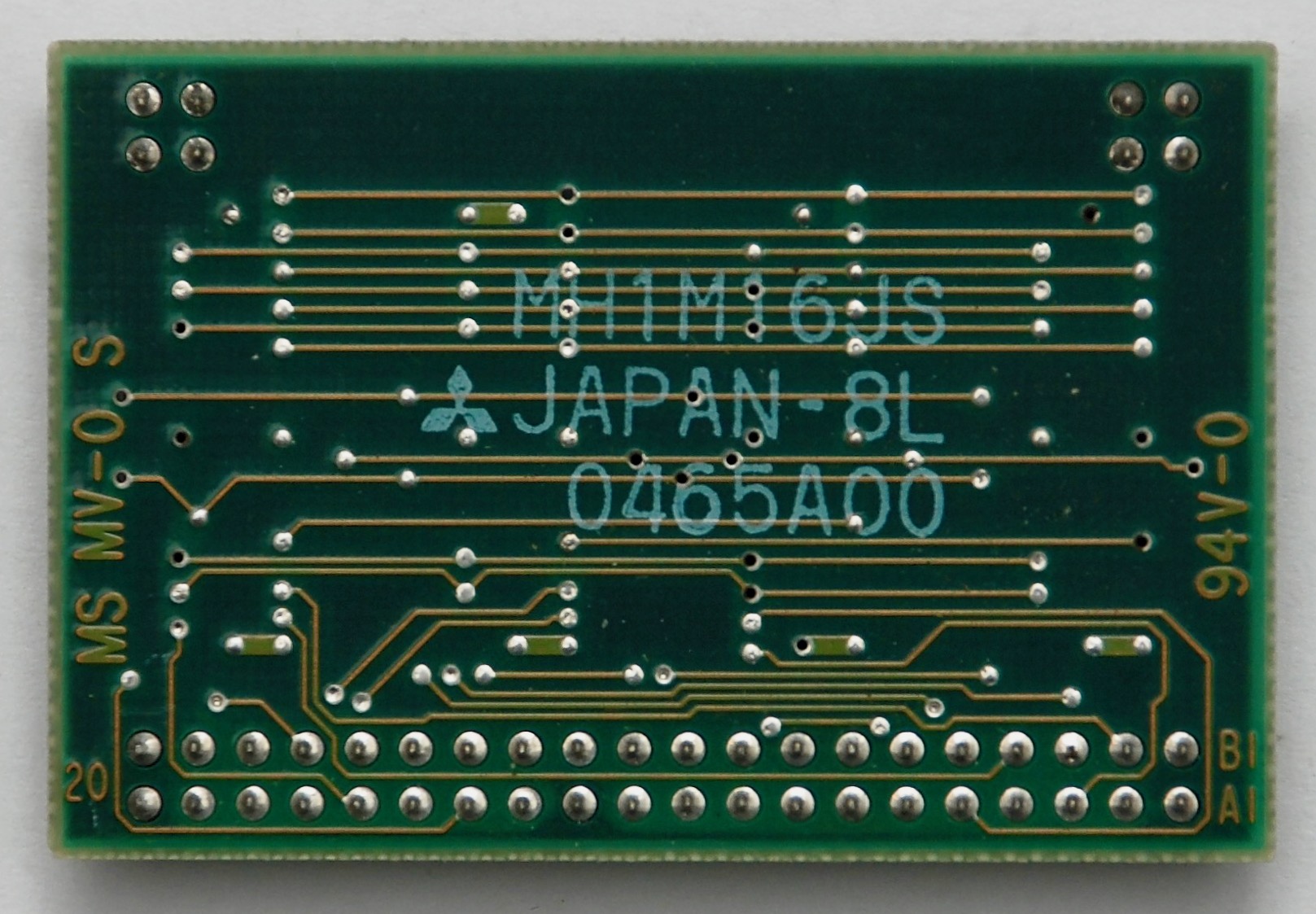
2MB Memory Module
Reverse-engineered schematic is available at my Github. This is a Mitsubishi MH1M16JS memory module.

LCD Screen
Sanyo LCM-5474


Backlight Power Inverter Module


Hard Drive
43MB Toshiba MK1122FC is HDD type 17 in BIOS.


Floppy Disk Drive
TEAC FD-335HF 063-U


LED Panel


Keyboard


BIOS
BIOS entry key combination is CTRL-ALT-ESC pressed after the system booted.


Power Supply
The original BIOS battery is AA-size 3.6V Lithium battery. It can be easily replaced with popular 1/2AA size 3.6V LiSOCl2 batteries.


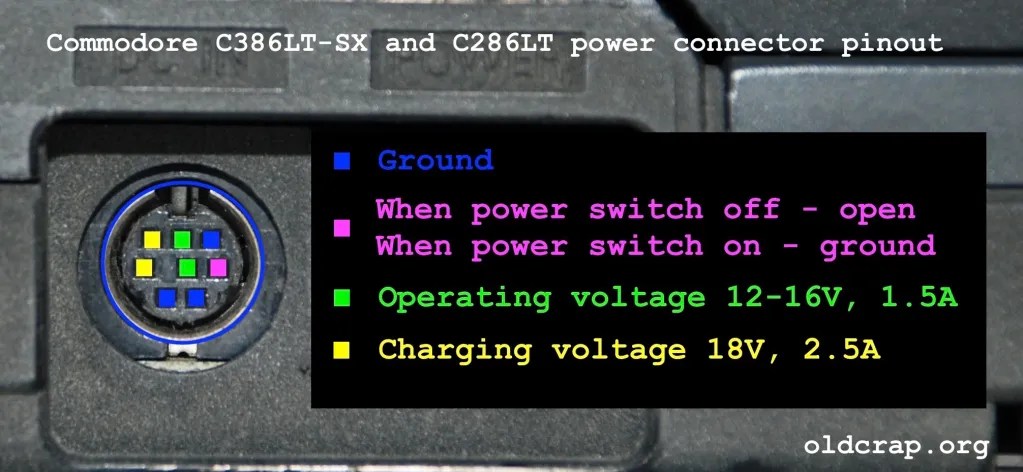
The power supply is pretty unusual and hard to replace. The pinout is described on the picture below. My laptop had the capacitors on the power supply board leaked. This caused the voltage to the LCD screen go out of the original range and turning the contrast wheel to the maximum contrast level provided voltage that actually killed the portions of the LCD panel – hence the dark vertical line on it.
If there is no need to charge the battery, it is possible to connect only +12V voltage and ground pins, for example from a router power supply that was described on the Atari SF314 FDD page. The power plug is Mini DIN 6-pin and is generally available today to purchase.


Battery
My computer came with no battery. For information about battery and its replacements, please see post about Commodore C286-LT. It is exactly the same in both models.
Reassembly


Grate ! Thank you. The power supply is the same of Shar
The same of which?
Hey Pawel, I just got my hands on the same machine. Mine is faulty, power supply sounds like it took a lighting hit. Do you have any schematics for it?
Hi. I don’t know where to get schematics for it. Do you mean the external power supply or the power supply board inside the computer?
Hi, I had the same prob with the contrast wheel. I changed the 7 black leaked caps on the power board. Now everything works fine.
Hi,
does anybody know how to switch to the external VGA out?
Is anywhere a scanned manual?
Has someone the original disks?
christian
Are you able to draw pcb schematic of 2MB memory module? I ask because i would like to draw new pcb and i’m not sure where 2×2 gold pins are connected. Btw. It seems that power supply unit is faulty and cause malfunction of one of OKI M52998 chips – see distorted rectangle on the display. Double check capacitors and make sure that voltage levels are correct.
I can do the schematic in some free time. As I explain in the text the panel got damaged from the faulty power supply.
It would be great to get schematic of 2MB board. You’re right, i missed that part about the screen and leaked psu capacitors. I wrote about OKI chips because i fixed damaged panel some time ago by replacing faulty chips. In my case 3 chips were faulty, in your case probably only one chip is damaged and need to be replaced. OKI chips are available at aliexpress.
Here you go: https://github.com/ppieczul/c386sx-lt-2mb-memory-module
There is no SOJ 26-pin footprint in the KiCad library, so it is just schematic. If you add a PCB to it, I have a kind request for you to share the files publicly. Good luck.
Hi Pawel, thank you for your work. I made few modules and works flawlessly.
Manufacturer: https://aisler.net/p/FVPDSCKQ
Result: (test boards with flux) https://postimg.cc/bG8bSprT
Wow, great job! Are you going to accept orders?
@Ace Ventura, what value caps did you use with your design? I seem to recall reading 1uF somewhere but other pages mention 100nF. Does it matter? They’re size 0805, right? Thank you!
@sugarzulu79, I used mix of caps from donor modules and the new one. I measured value of desoldered caps between 680nF to 970nF. The new caps I used 0805 size with 1uF.
@Pawel Pieczul, If you or anyone is interested, I have 4 assembled modules for sale. 2 pcs with HY514400AJ-70 and 2 pcs with OKI M514400C-70SJ chips. I would ask 5€ per module + shipping.
@Ace Ventura are you still selling those memory modules?
I was trying to fix my floppy drive, then came across this site once my LCD also died.
I think it is 1 chip as well, I purchased 4 on Aliexpress and will try to replace it.
I also ordered some PCBs from the design Ace Ventura posted before I noticed he had some populated ones for sale.
Thanks for this great source of information! The only part I am missing from the laptop is the power supply, for now I have wired up a 12V PSU to the battery contacts, also working on wiring one to the DIN connector.
In terms of my floppy drive, it is almost working.. it works if I apply very slight pressure to the upper read head. I’ve been using Image Disk to re-align the heads since I had a dissassembled floppy drive to start with.
Again, thanks everyone for the comments here.
@Ace Ventura, you still have those for sale? please message me at alex@moir.pw
Wow that was very fast. Thank you. I will publish pcb when it’s done. Btw. Contact me (send an email) if you’re interested in fixing the display.
Hi Christian,
To switch to external monitor you need to use DOS utility. I have it somewhere on the disk 😀 There is no other option to do that.
I have got oryginal HDD but it is useless. To many not marked Bad Blocks…
I used Compact Flash adapter with 2GB card and it is working perfectly. But you need to use EZ-DRIVE utility to prepare bootloader and format the Card. I also successfully tested SD adapter with 4GB card.
I can prepare manual for both tools and share files.
Hi, I have recently acquired the ZEOS version of this laptop. Did you happen to find the utility to switch to external monitor? My machine currently has a dead backlight but otherwise in perfect working order. It would be nice to be able to actually use it with an external display until I can work out how to fix it properly.
Regards
Mike
Hi. I haven’t tried the external port and don’t know how to enable signal there. Maybe other people commenting here know something?
I uploaded the eagle.com utility for external VGA output and other drivers that I have for the C286-LT and C386SX-LT to archive.org.
Did you get anywhere with the PCB design? I was looking at having a go at putting one of these together myself as well
Hi Grzegorz
Could you explain how did you replaced OKI chips. Im about to fix my display but in don’t know if it’s safe to use heat gun on PCB with lcd still attached to it on the other side or do I have to disassemble everything.
I just did that today. I added flux and low-melt (leaded) solder on the pins of the chip to be desoldered (just with a normal soldering iron), then with a hot-air station (340degC and 70 airflow) I melted the solder and lifted the chips. I did it a few times (since only the 3rd M5299B was actually functional – good thing I ordered 4 chips from aliexpress) without damaging the LCD. The screen is now fixed with 2 replaced OKI M5299Bs.
I would NOT use heat gun, you will burn and bake the PCB and damage the LCD.
Good luck!
I have the same computer, but from Sanyo model MBC-18NB6h (the case and components are identical).
I have a problem that every time I start up I get the message:
“Invalid configuration information – please run setup program
Press the F1 key to continue, F2 to run the setup utility”
After entering the BIOS via the F2 key and saving the configuration I have the message each time:
“SETUP has attempted to correct the following errors:
* Standard CMOS checksum was invalid. Standard CMOS were loaded.
* System configuration was invalid. Review the first page settings.”
The CMOS battery is functional – the clock and calendar work.
Does anyone know what the problem could be?
Translated with http://www.DeepL.com/Translator (free version)
I ve got the schematics and service manual of the 286 version, but the 386sx is almost identical due to same chipset (for which i also have all informations…)
I also did a lot of mods the last 30 years since i came across with this model first time working at sanyo (which is the real manufacturer of these units, commodore and Zeos are just OEM versions!)
So it is possible to have up to 8 MB RAM instead of only 5MB (with some more effort also 16 MB( 15MB usable) is possible, but upper 8MB is SRAM then due to limitations of the chipset).
There are different BIOS versions not only for the OEMs, but also between 286 and 386 models.
It is possible to have a second COM: port with rather small effort the same like an external PS/2 Keyb.-Connector (working in parallel with the onboard keyboard!) and Networking, sound or even general PCMCIA can be integrated e.g. instead of internal Floppy-drive as there are all ISA-Signals available on the mainboard!
The internal power-supply with leaking condensors should be repaired rather quickly to avoid damage on the LCD-Boards, that i can prove.
Also the bulky external power supply gets faulty quite often, but is repair-friendly 🙂 if you know how switched power supplies work. Keep out of this box if not, it has dangerous voltages inside, even hours after disconnecting it from mains!!!
I managed to get a quite modern “chinese” TFT running and mounted internally, but it takes the VGA analog signal, so it could be even more improved by modding the digital out (which at the moment is restricted to grayscale VGA panels…) But as 4:3 VGA/SVGA TFT panels get more and more rare, this is also not an long term option…
The tools needed for switching between internal and external screen are from OAK and often are called “eagle” as this was the internal name of the VGA-chipset at that time… (i ve these tools too..)
Currently i am working on a relaunch of my personal website, where i will place all that information and stuff, so at the moment please send private message for any question.
Do you have a schematic of internal power-supply to the C386SX-LT?
Unfortunatelly not.
Could someone please confirm that the C386SX-LT expects the BIOS battery to be a NON-RECHARGEABLE lithium battery? The datasheet for the replacement BIOS battery suggested by the article mentions that it is a non-recharge battery. Now I am unsure if it’s safe to plug in a non-rechargeable if the laptop would try to charge it when plugged into the laptop charger. (I’m basing my assumption on most 386/486 motherboards of the ERA having rechargeable VARTA NiMH “barrel” CMOS batteries). Thank you!
Yes, you need to use non-rechargeable battery cell. I used SAFT primary cell LS14250 as replacement.