


Resources
Wiki
ROMs and ROM guide
old-computers.com
Documents
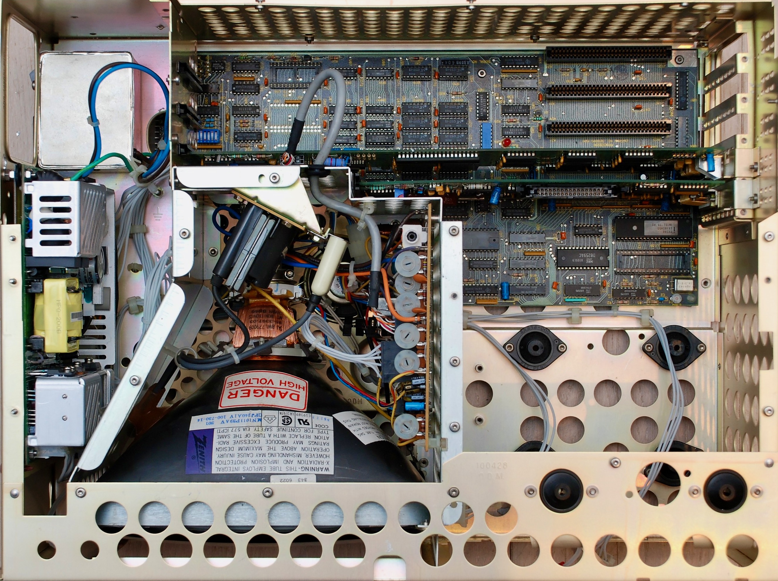
Internals
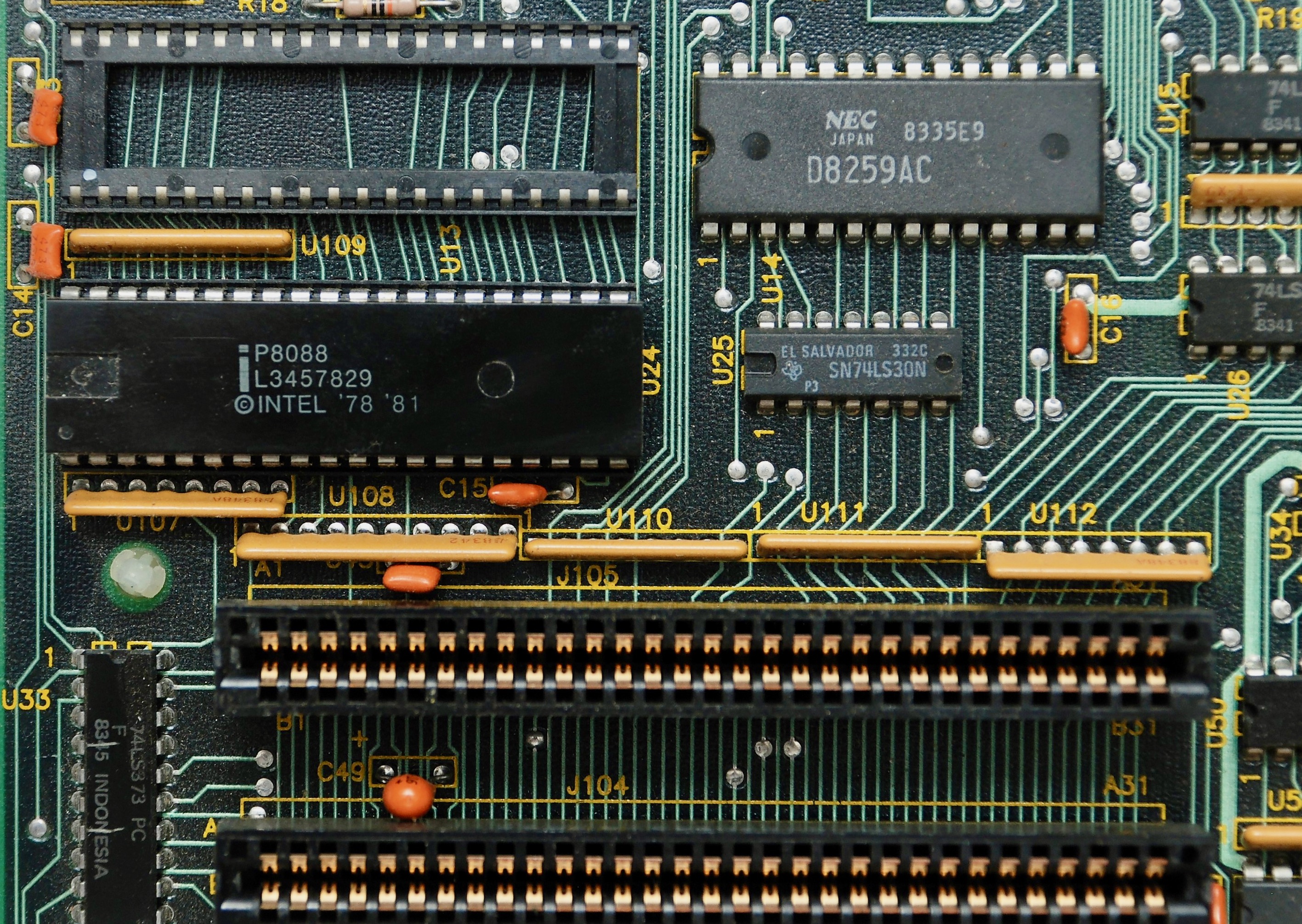
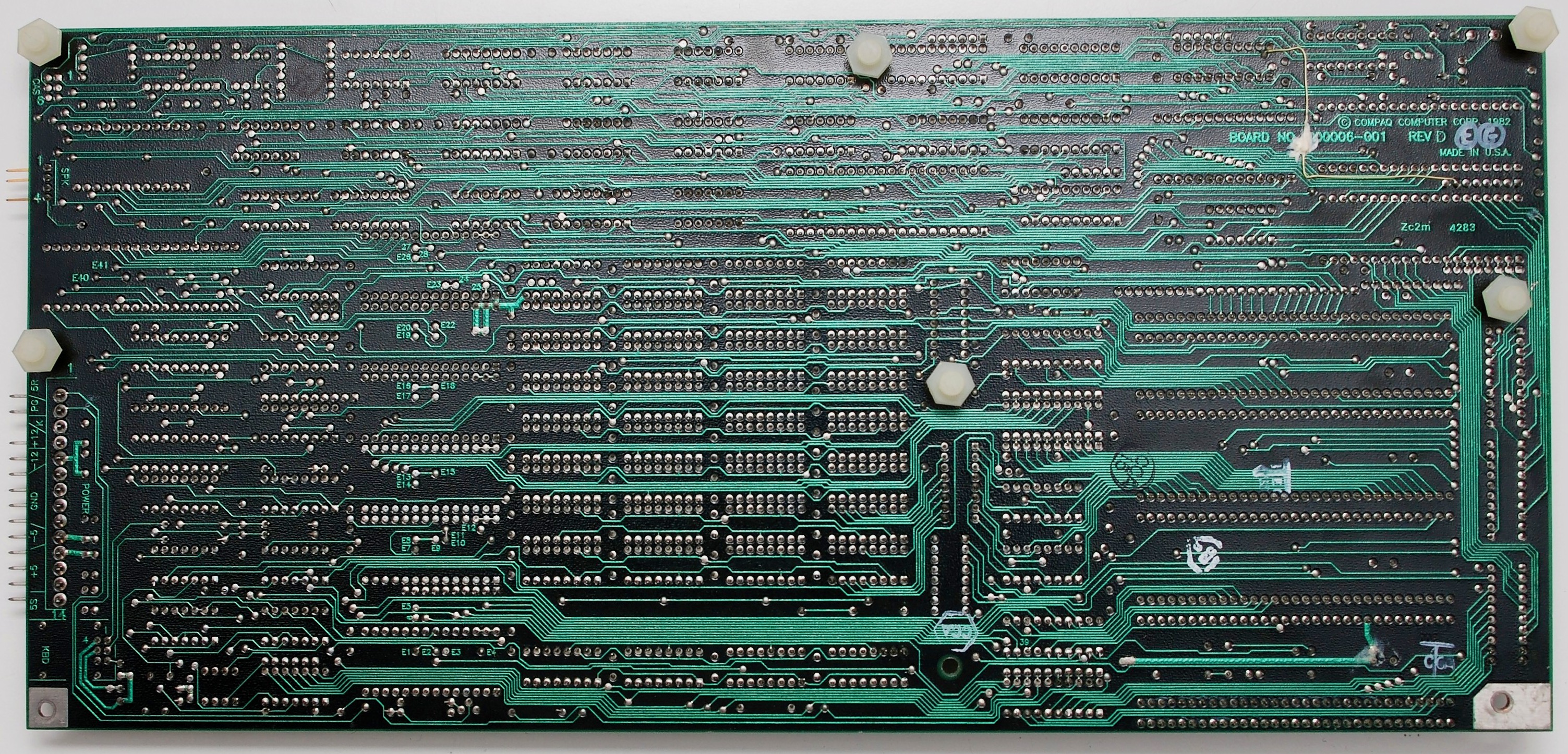
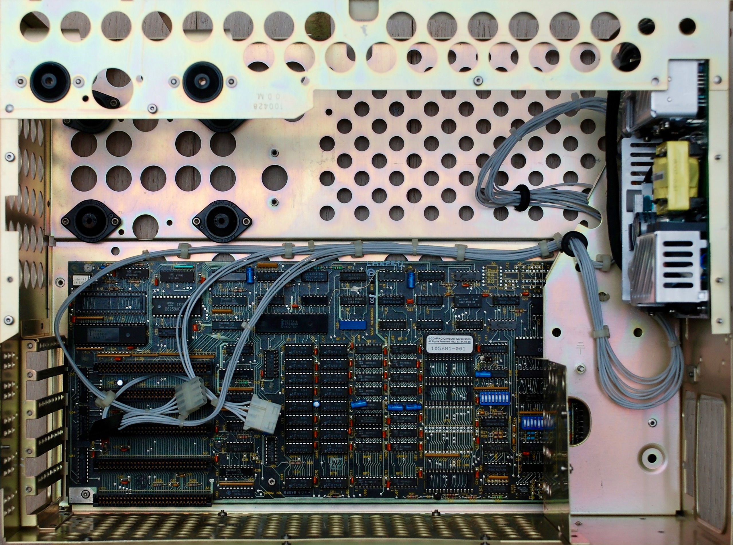
Motherboard
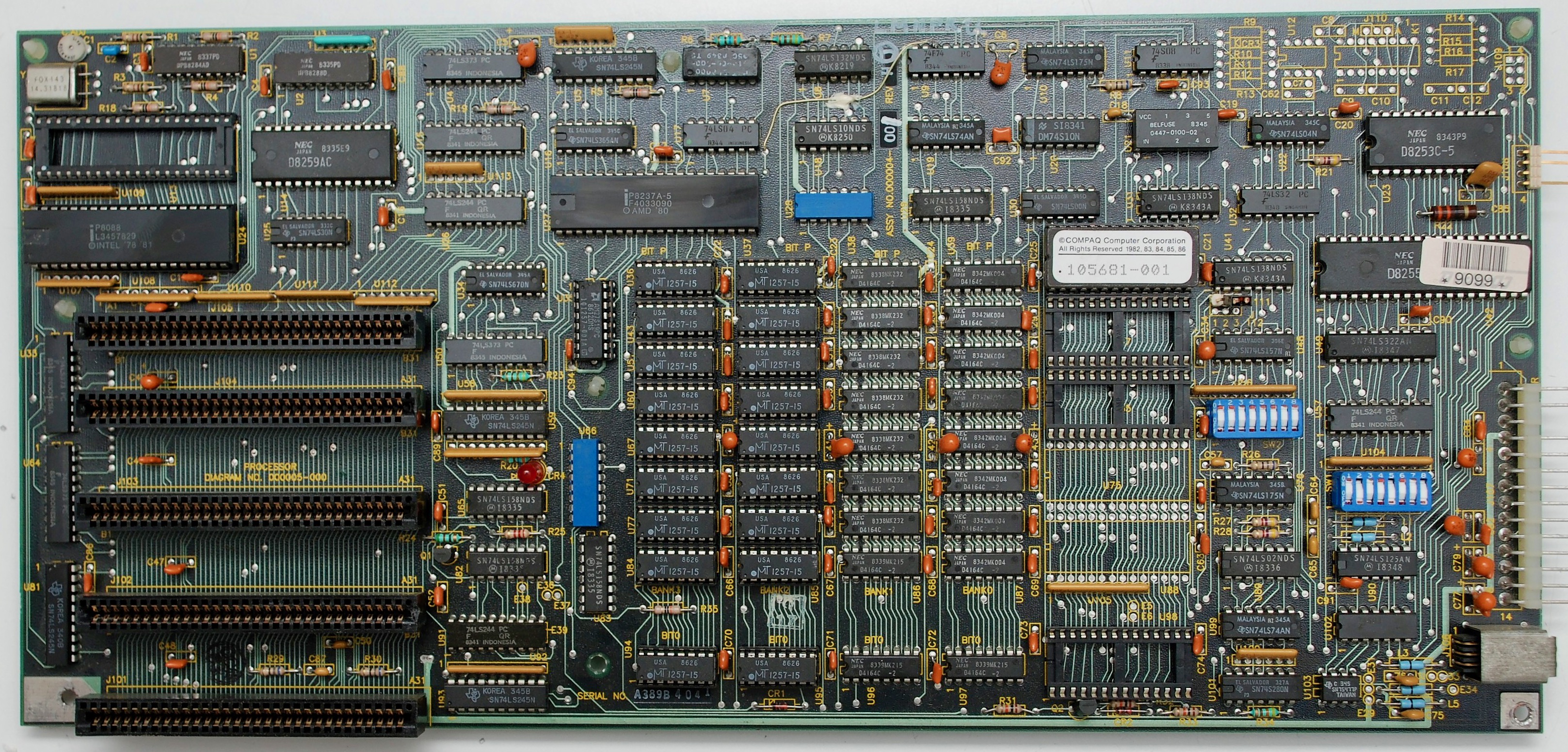
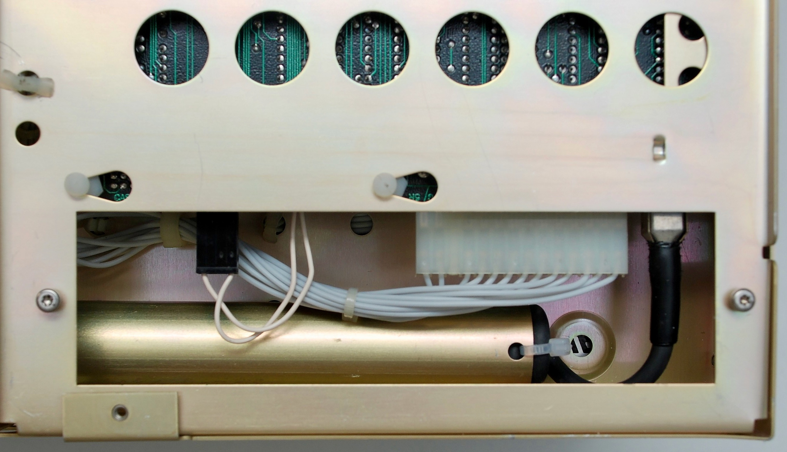
The motherboard and ISA cards contain tantalum capacitors, which are prone to failure and shorting the power lines to ground. It is a good idea to replace all polarised tantalum capacitors, for example with modern electrolytic capacitors.

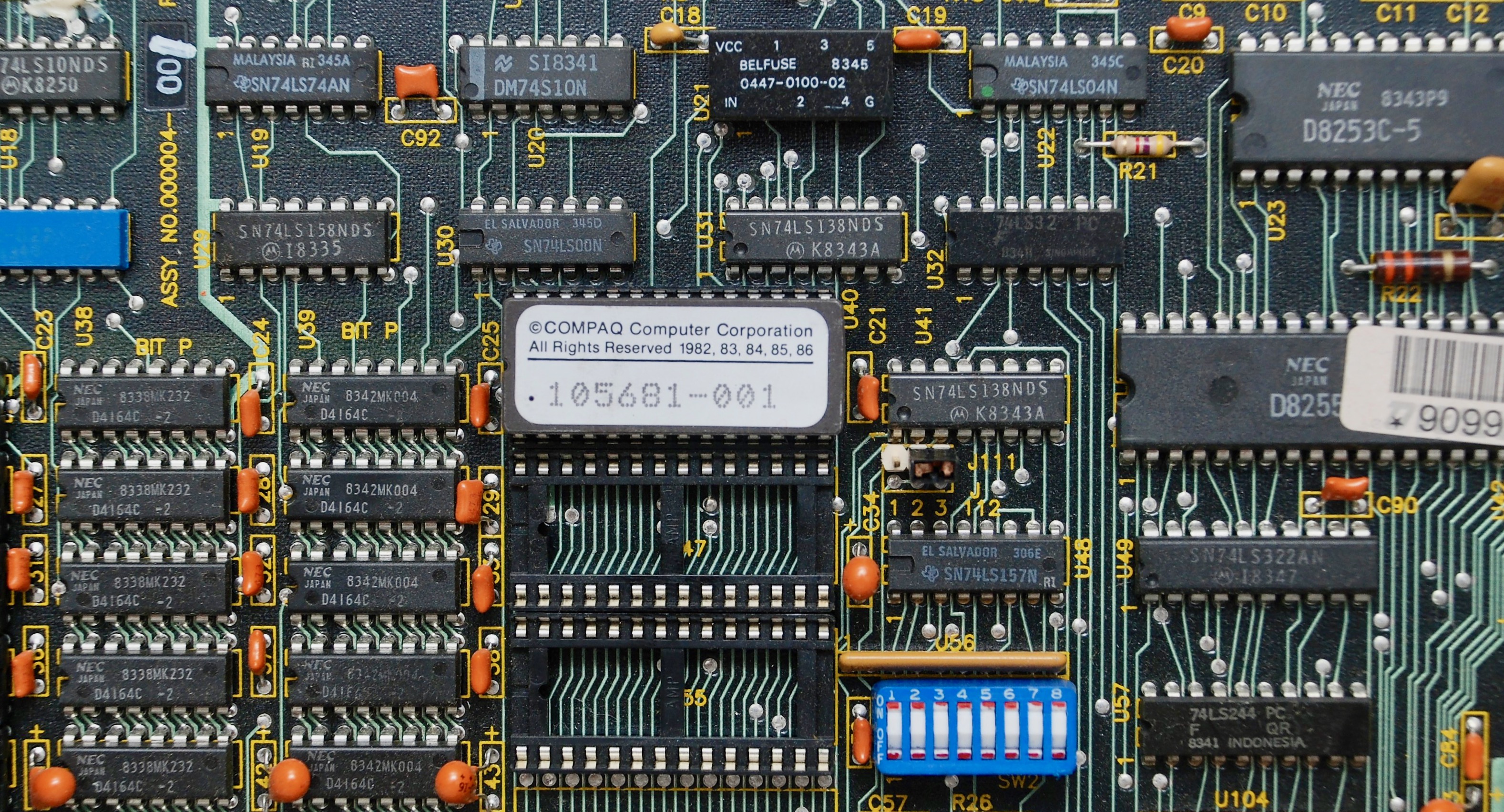
Jumper Settings
| SW1 | Meaning | Values | Result |
|---|---|---|---|
| 1 | reserved | OFF | always |
| 2 | coprocessor | ON | not installed (default) |
| OFF | installed | ||
| 3 | reserved | OFF | always |
| 4 | reserved | OFF | always |
| 5,6 | display mode | ON,OFF | 1: internal 80×25 2: external monochrome (default) |
| OFF,ON | 1: internal 40×25 2: external monochrome | ||
| ON,ON | 1: external EGA over RGBI 2: external monochrome | ||
| OFF,OFF | 1: external monochrome 2: external RGBI | ||
| 7,8 | FDD setup | ON,ON | 1 FDD installed |
| OFF,ON | 2 FDDs installed | ||
| ON,OFF | 3 FDDs installed | ||
| OFF,OFF | 4 FDDs installed |
| SW2-1 | SW2-2 | SW2-3 | SW2-4 | Installed memory Switches 5 to 8 always OFF |
|---|---|---|---|---|
| ON | OFF | ON | ON | 128 KB |
| ON | ON | OFF | ON | 192 KB |
| ON | OFF | OFF | ON | 256 KB |
| ON | ON | ON | OFF | 320 KB |
| ON | OFF | ON | OFF | 384 KB |
| ON | ON | OFF | OFF | 448 KB |
| ON | OFF | OFF | OFF | 512 KB |
| OFF | OFF | OFF | OFF | 544 KB |
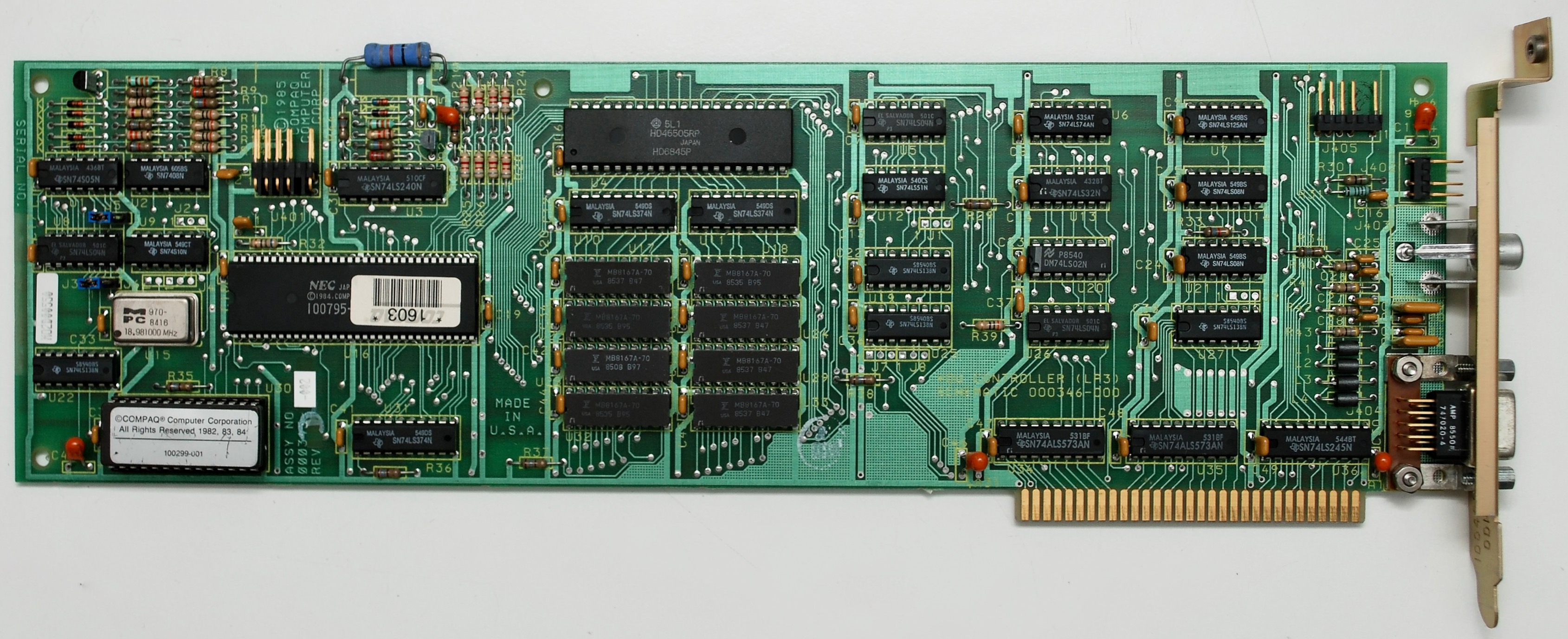
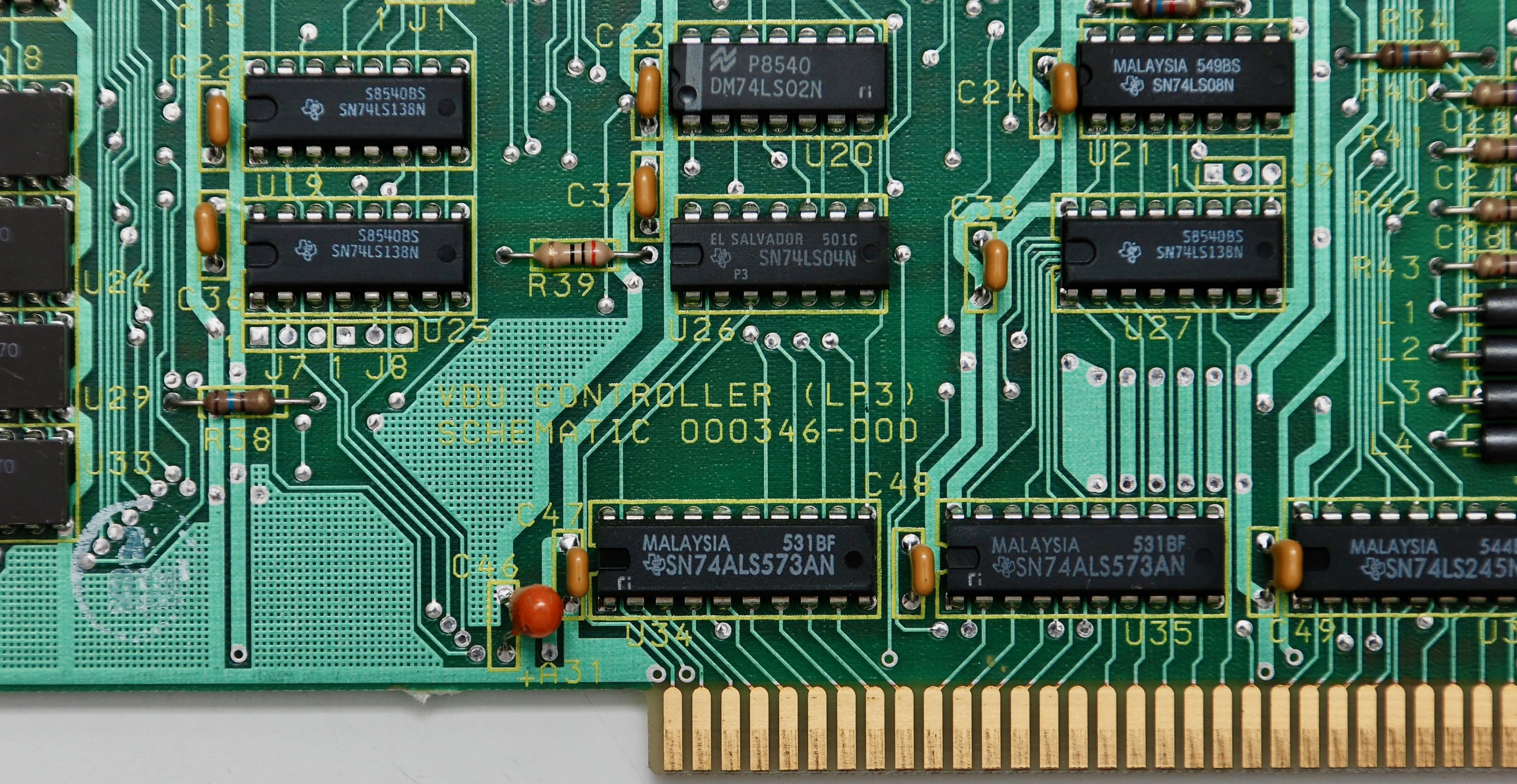
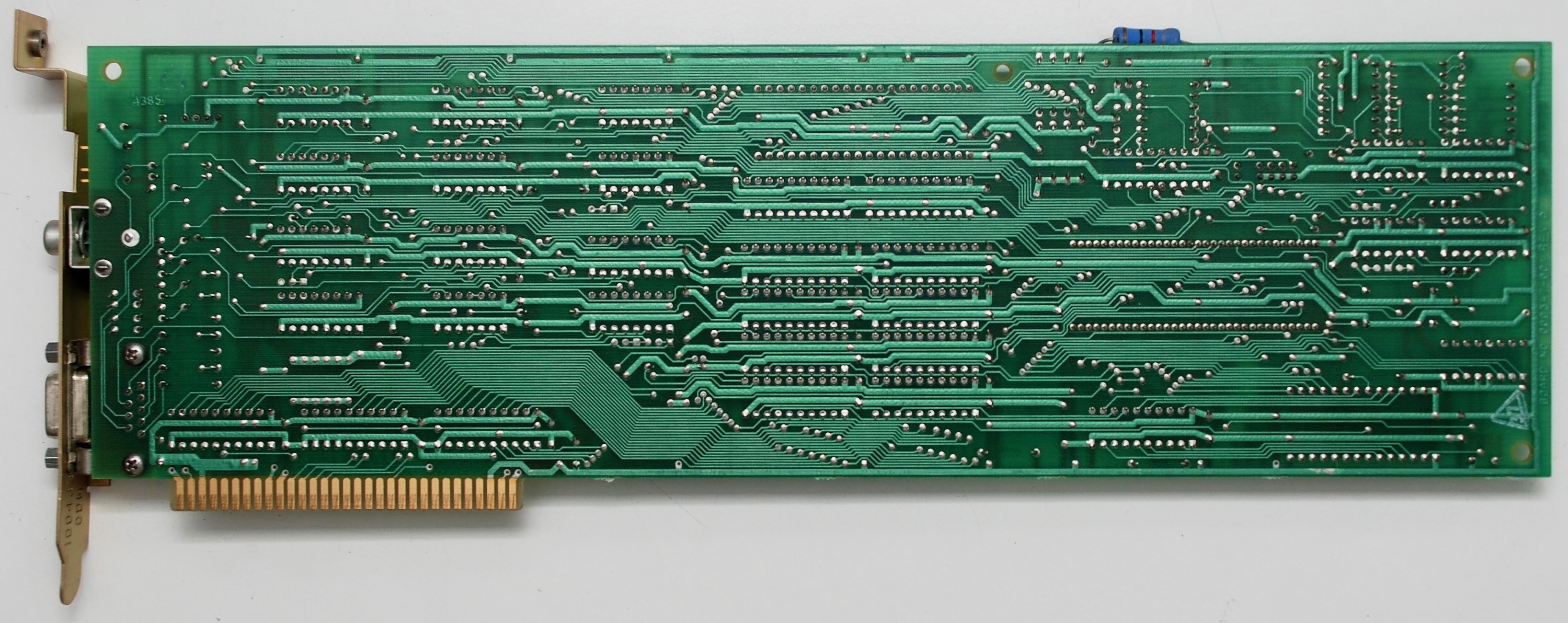
Video Display Adapter (VDU)
Jumper Settings
| Jumper | Value | Result |
|---|---|---|
| J3 | 1-2 ON | External composite and RGBI sync disabled Can be enabled with CTRL+ALT+< |
| 2-3 ON | External composite and RGBI sync enabled | |
| J5 | 1-2 ON | External RGBI video disabled Can be enabled with CTRL+ALT+< |
| 2-3 ON | External RGBI video enabled |
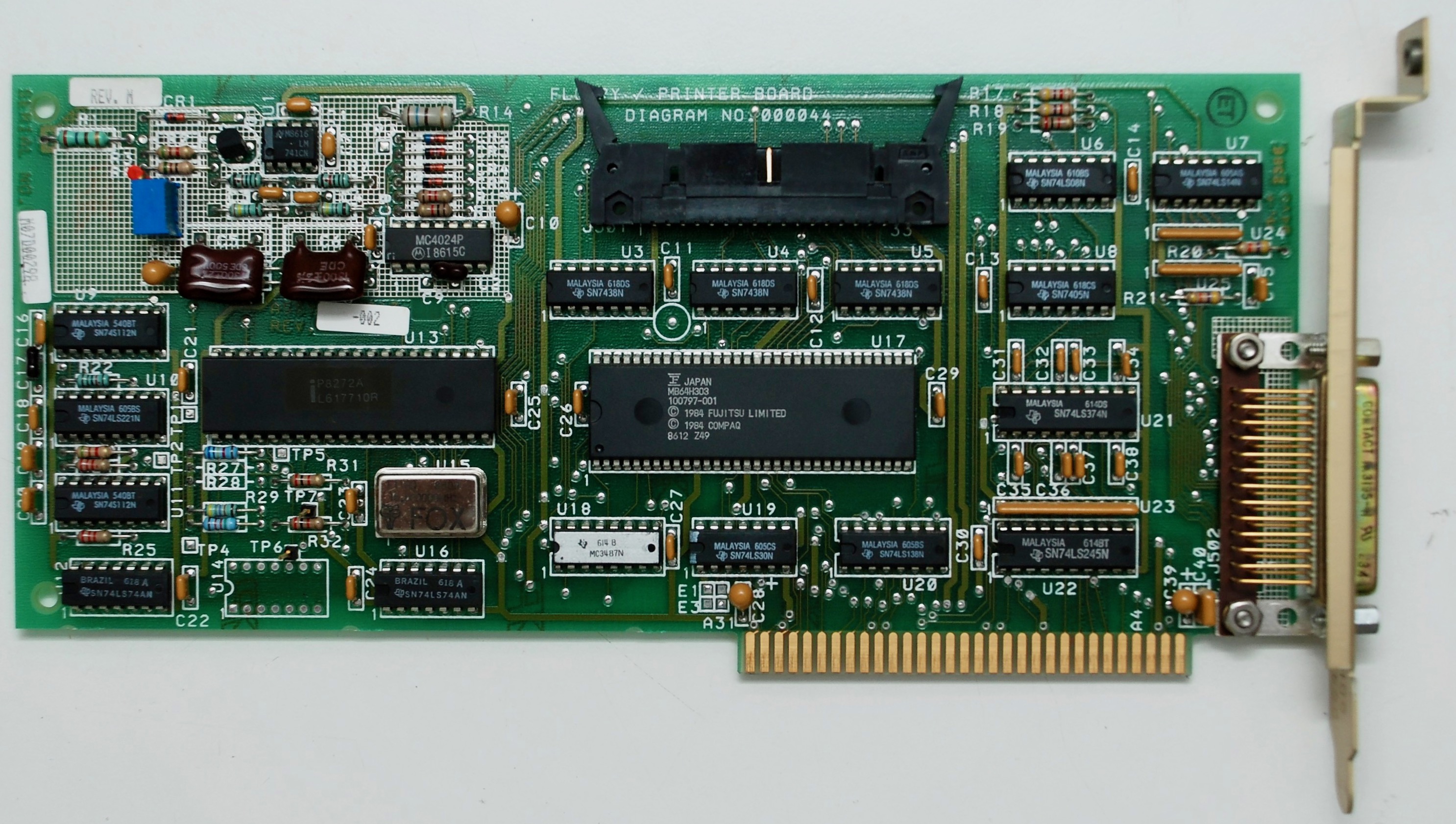
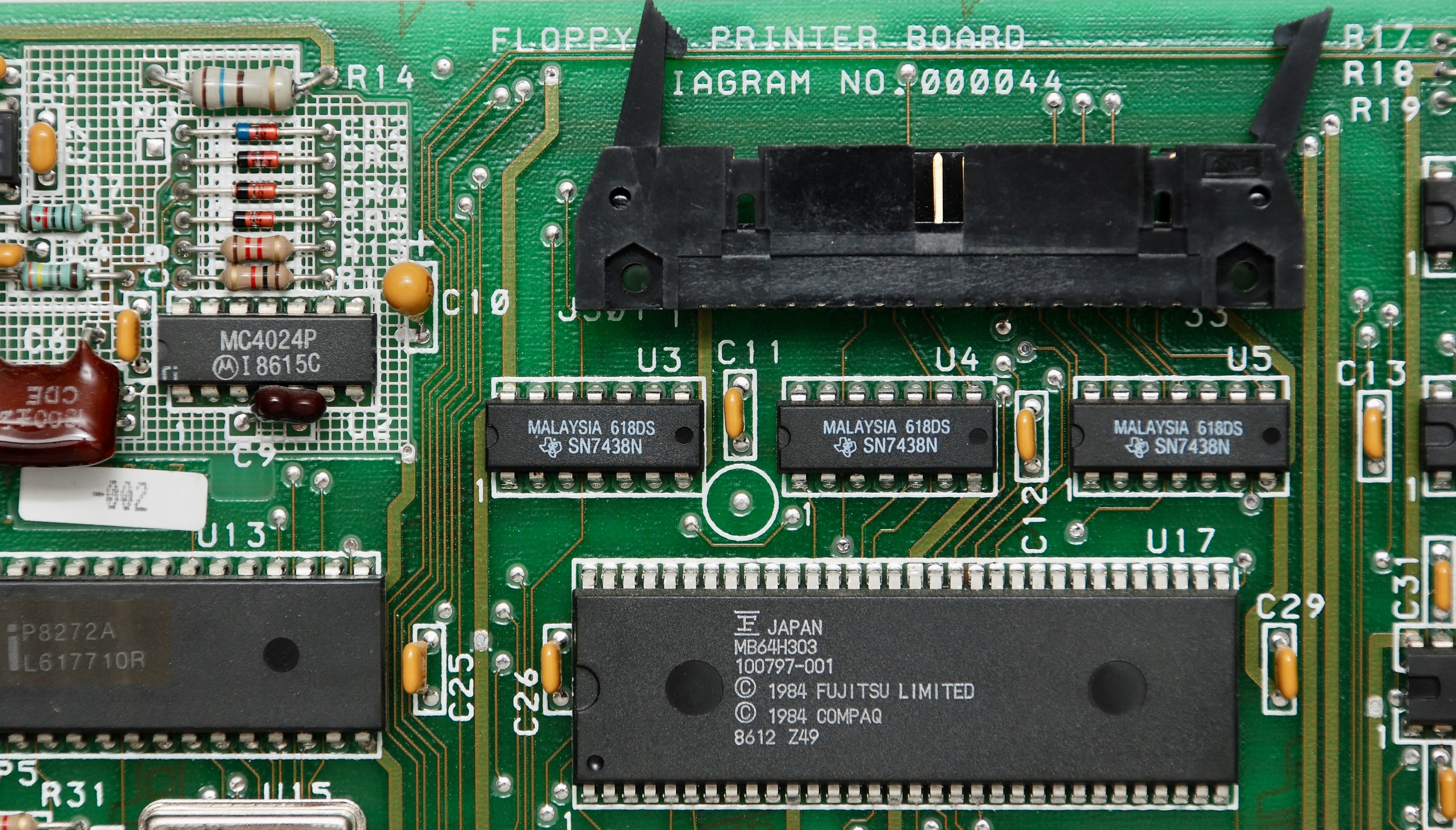
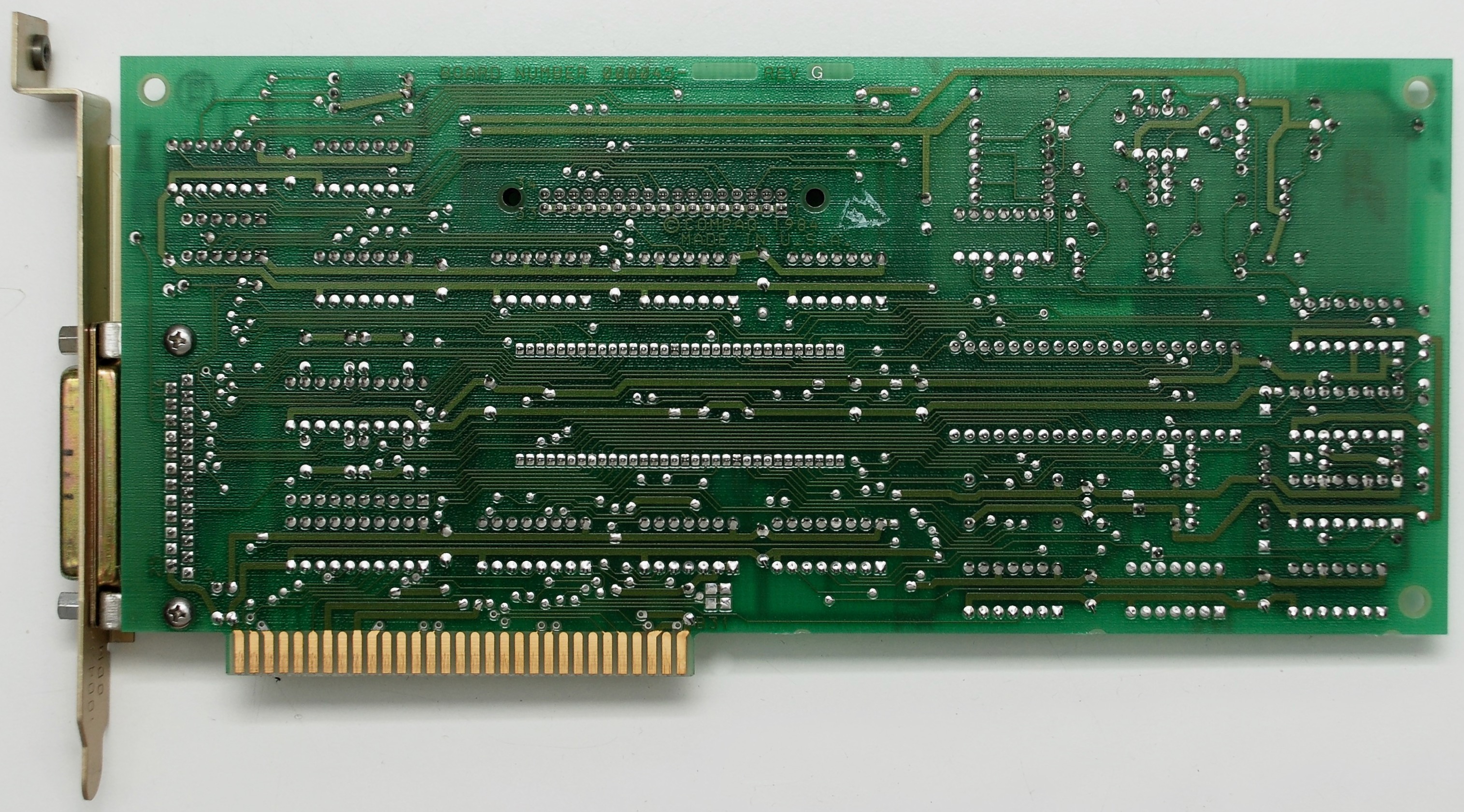
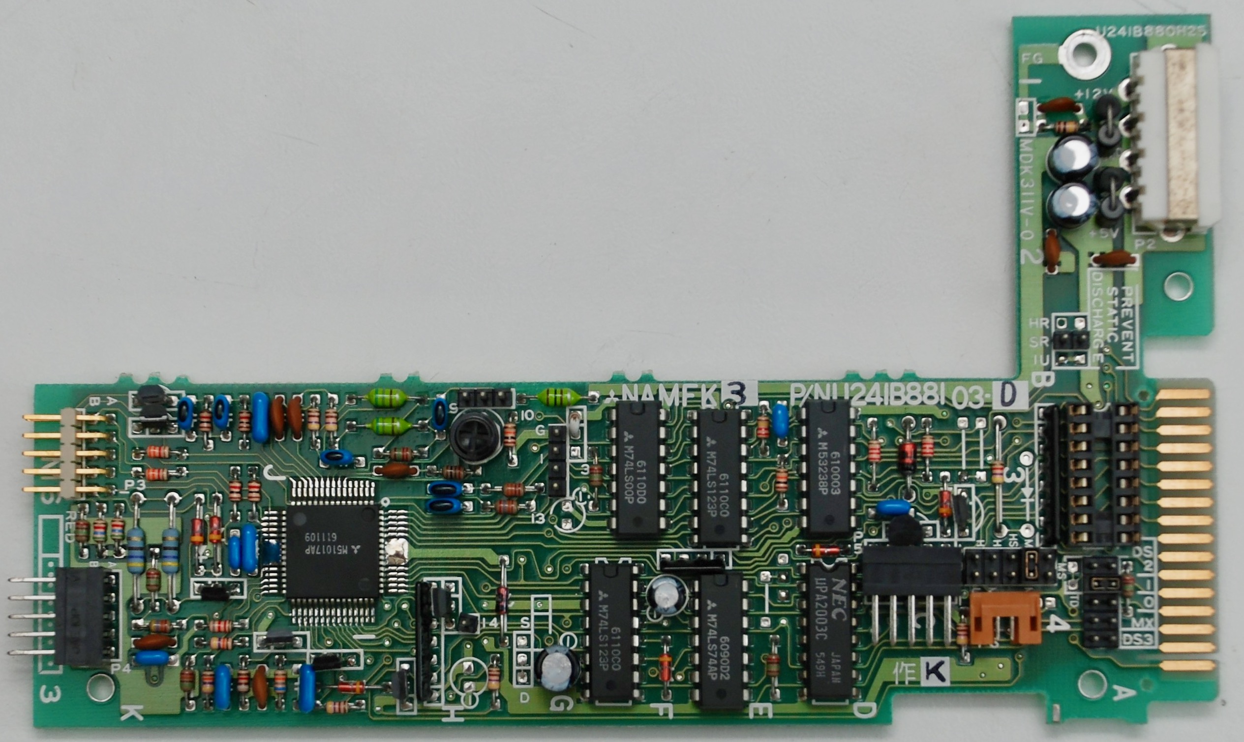
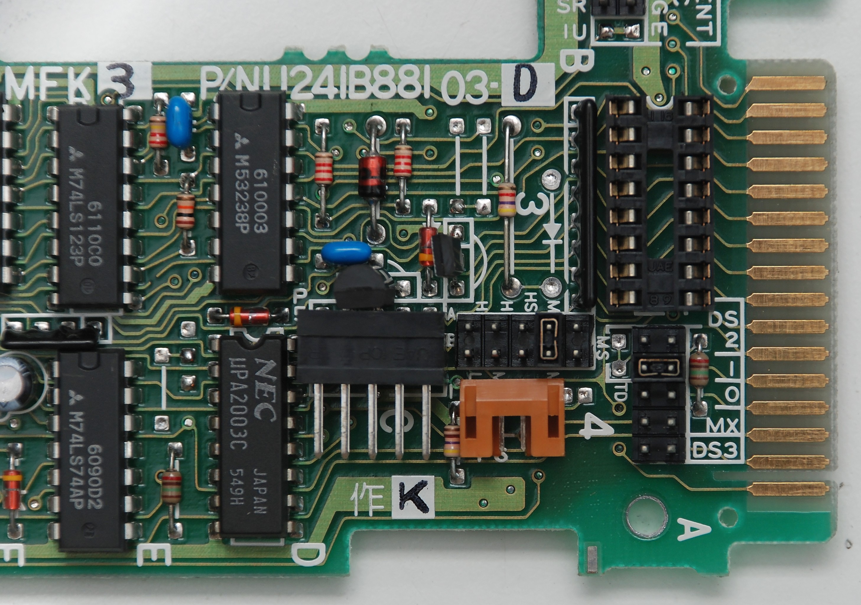
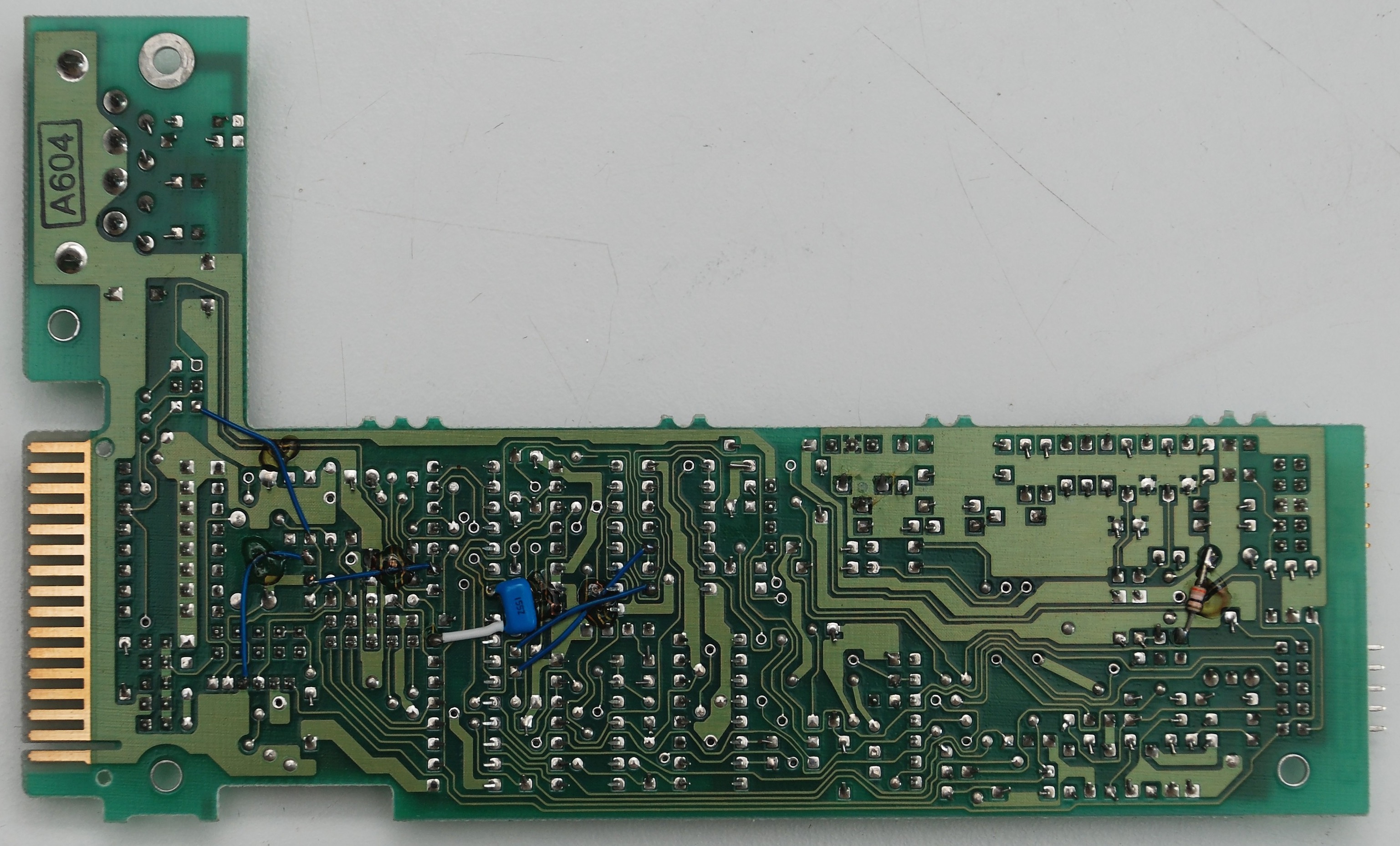
Printer and Floppy Adapter
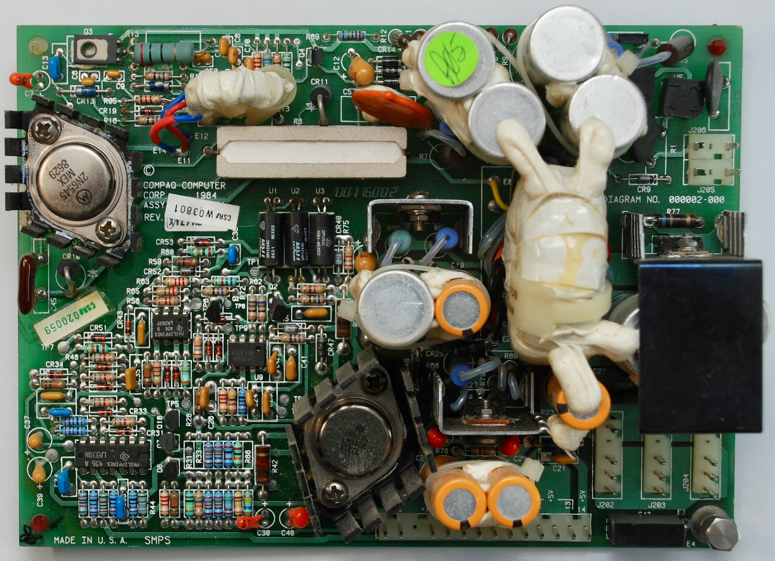
Power Supply
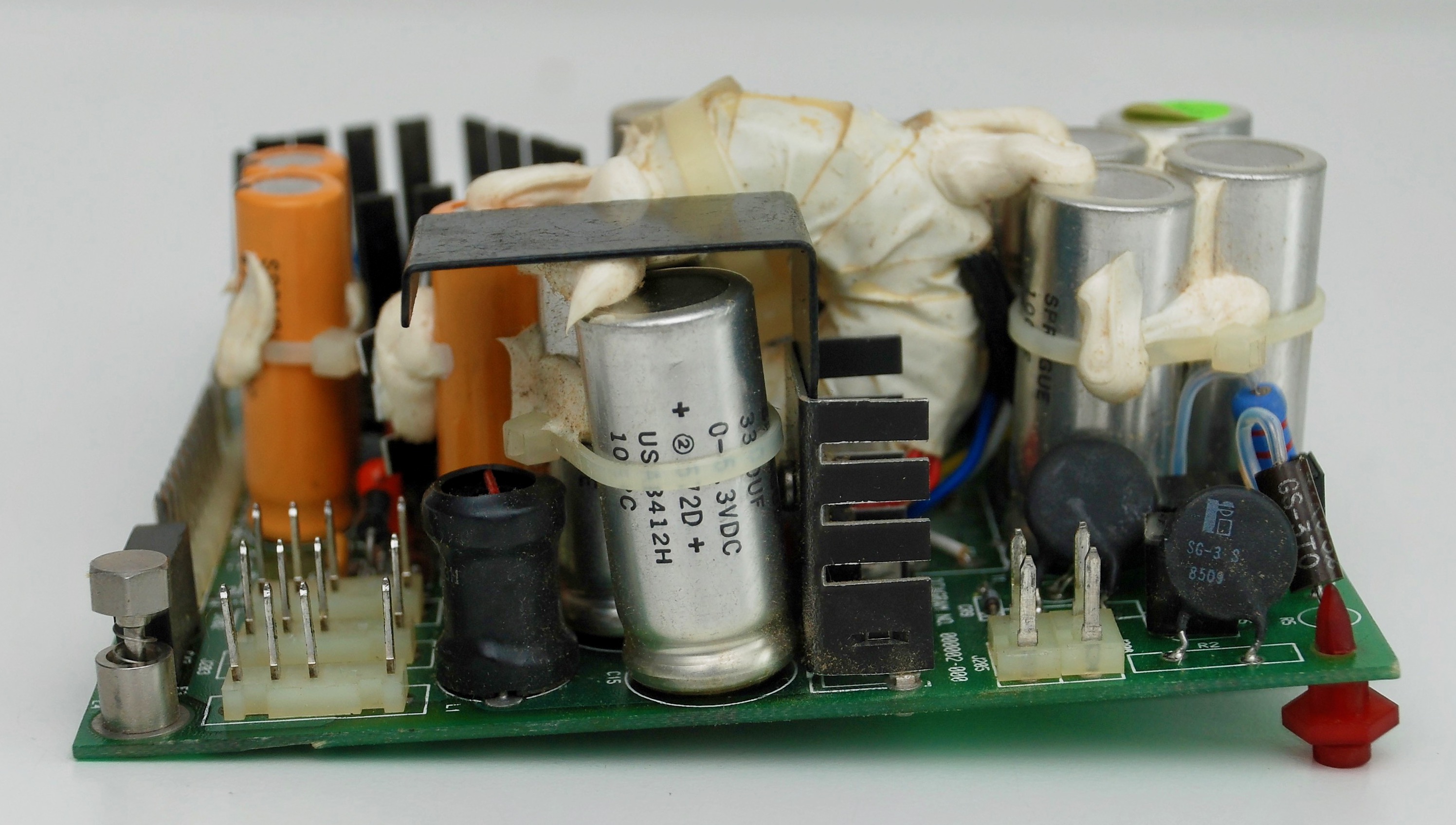
Instructions on replacing the original power supply with a modern one are towards the end of this post.
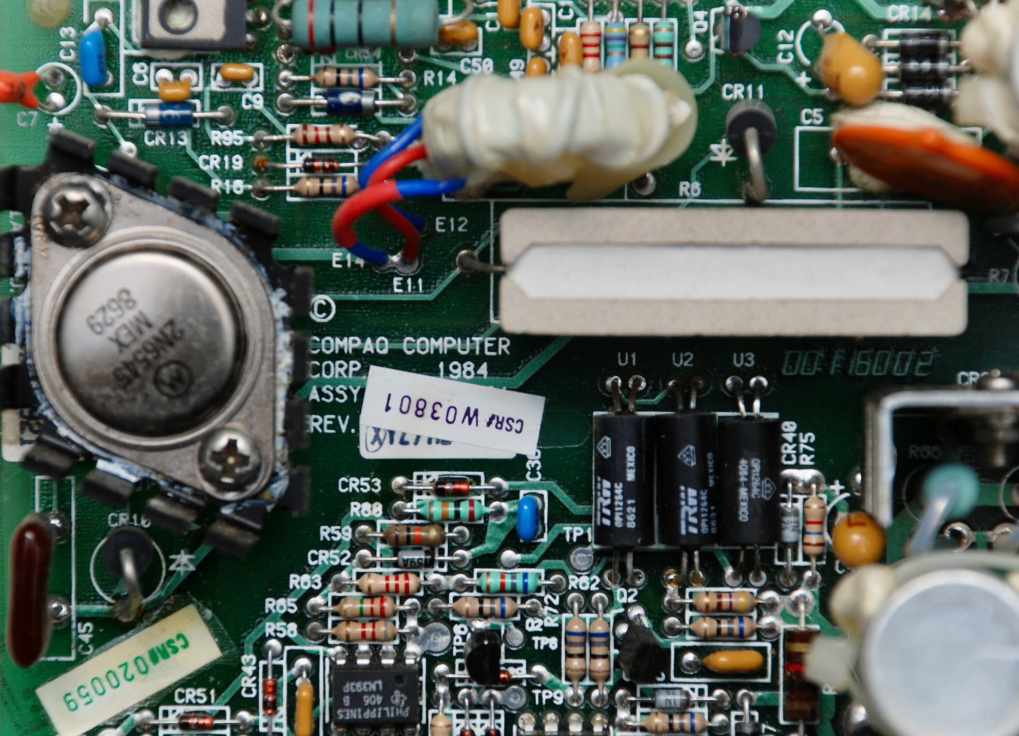
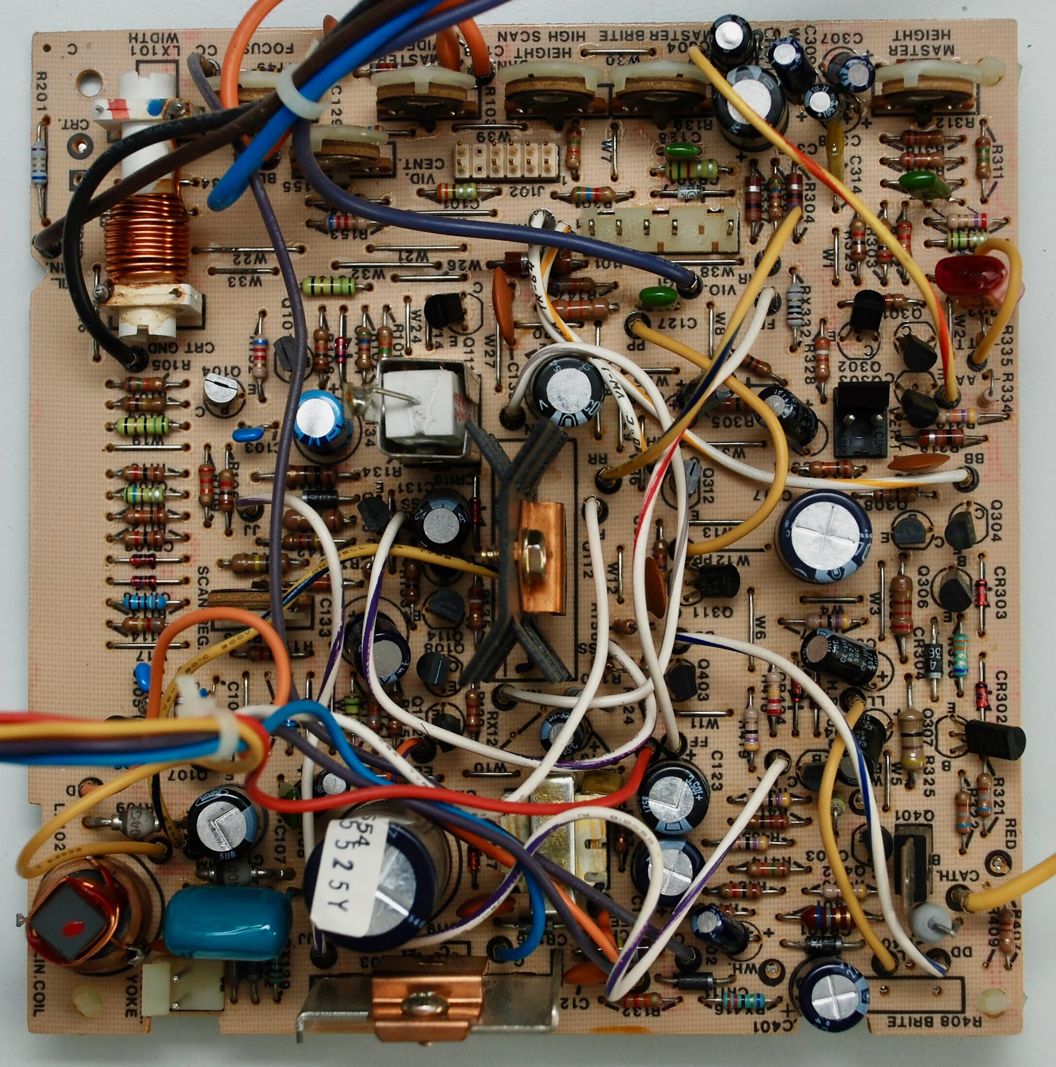
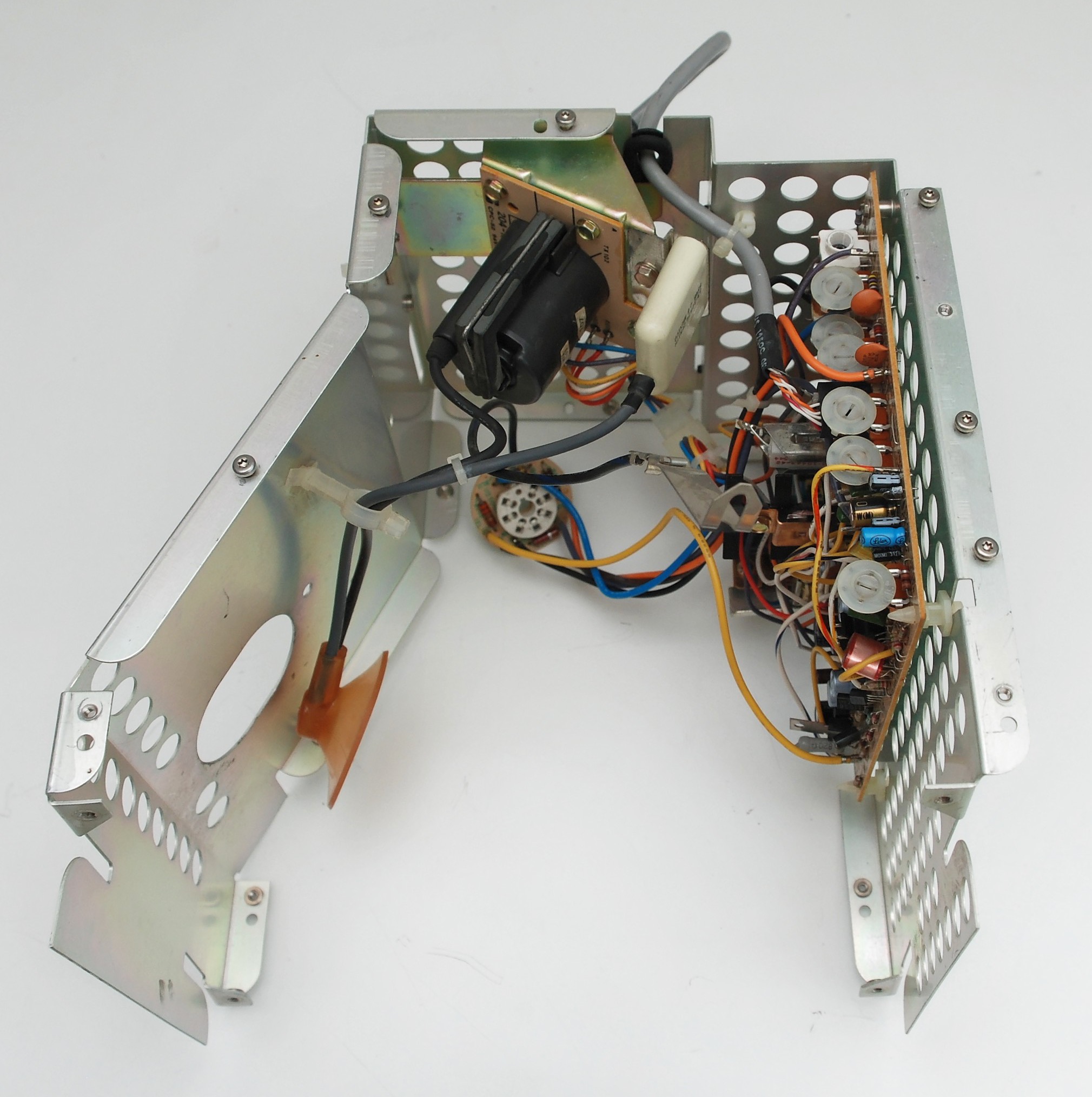
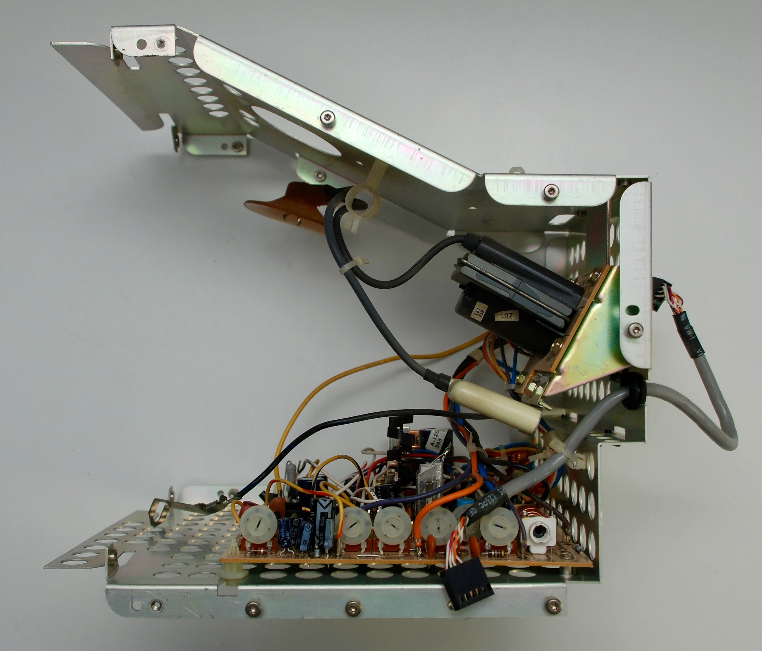
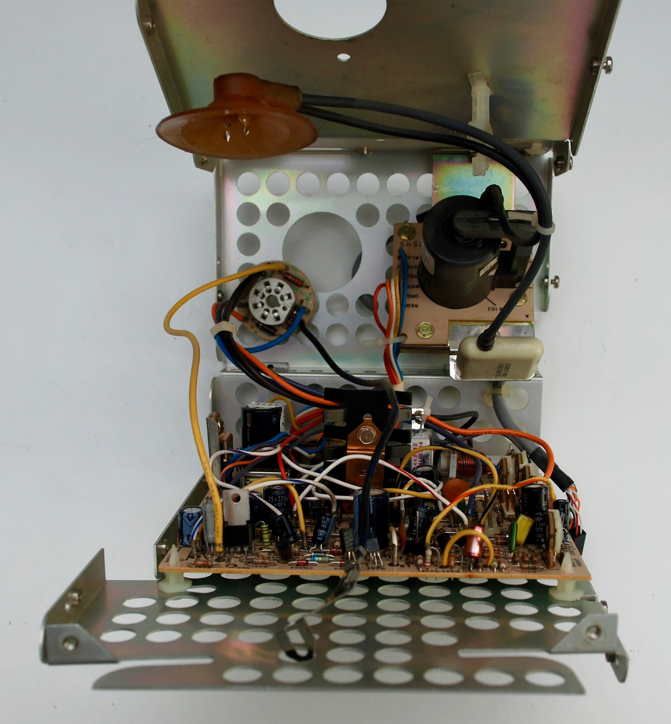
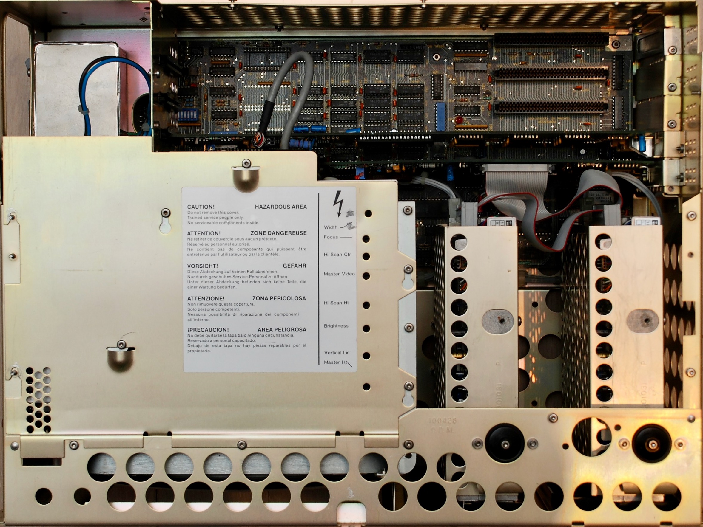
Analog Board
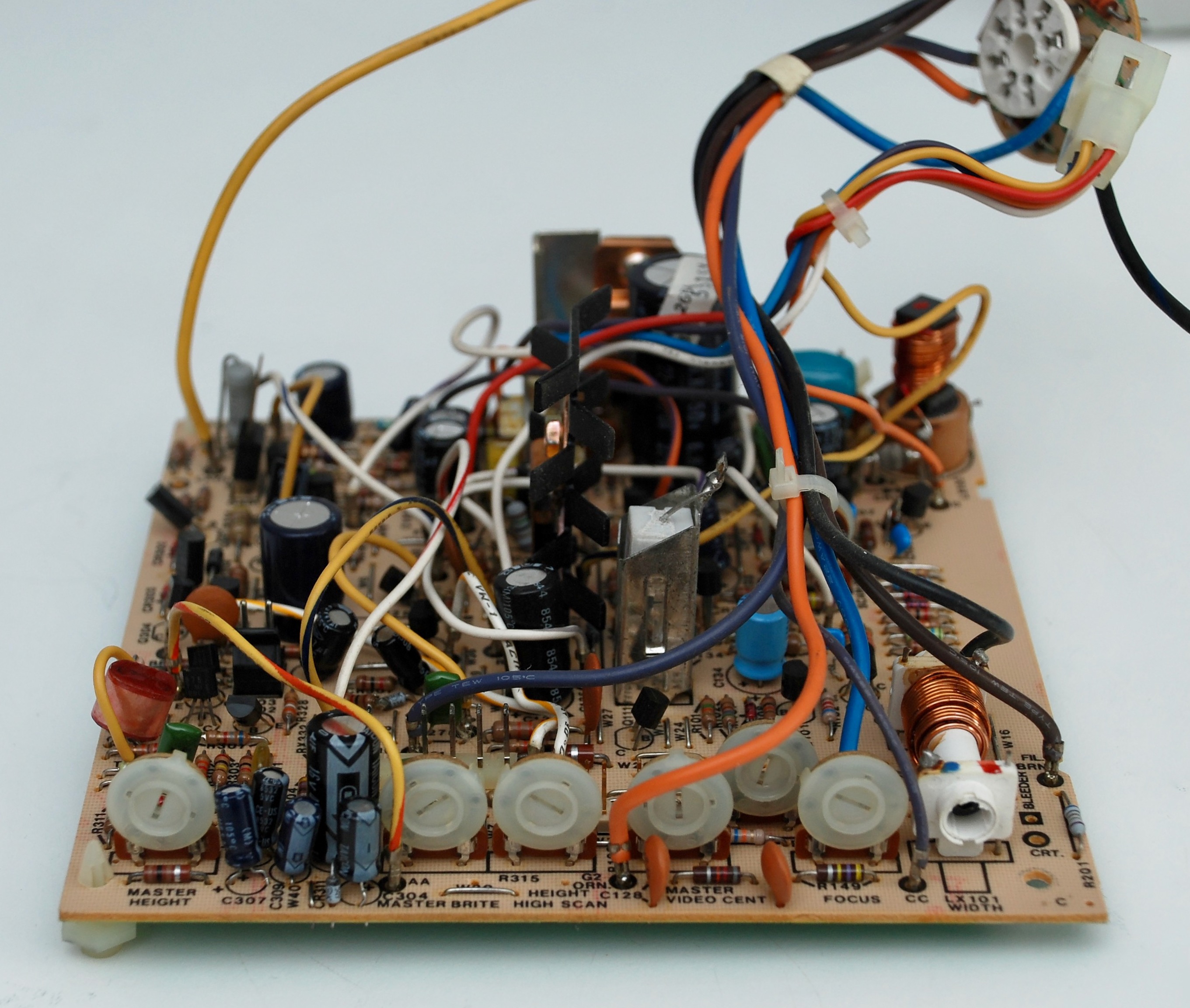
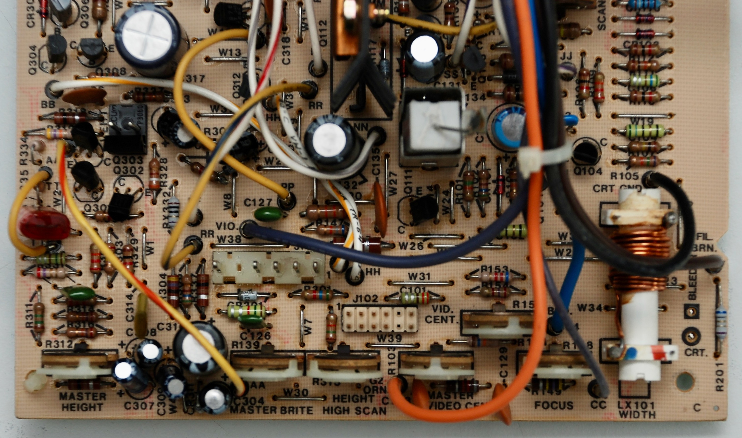
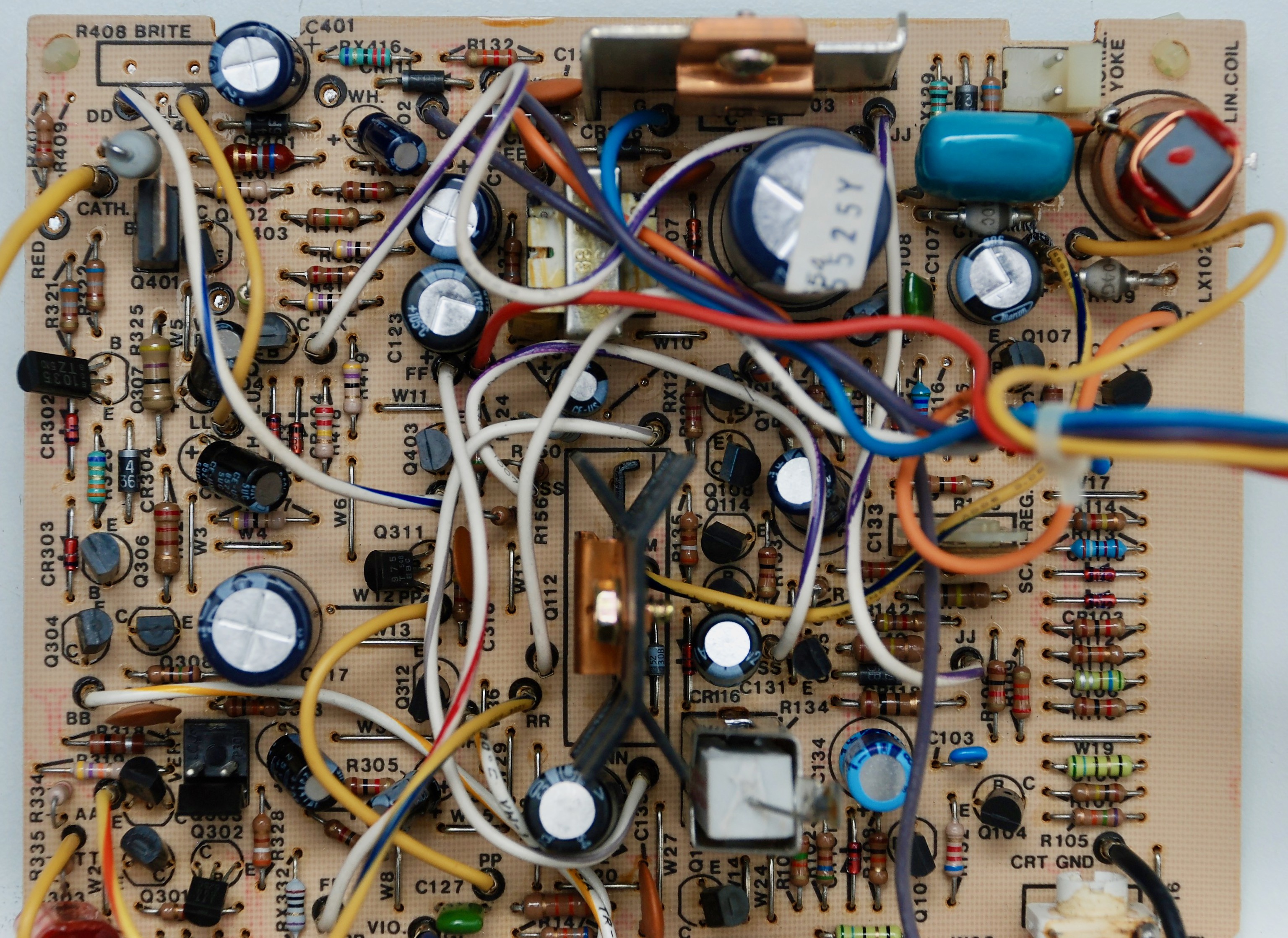
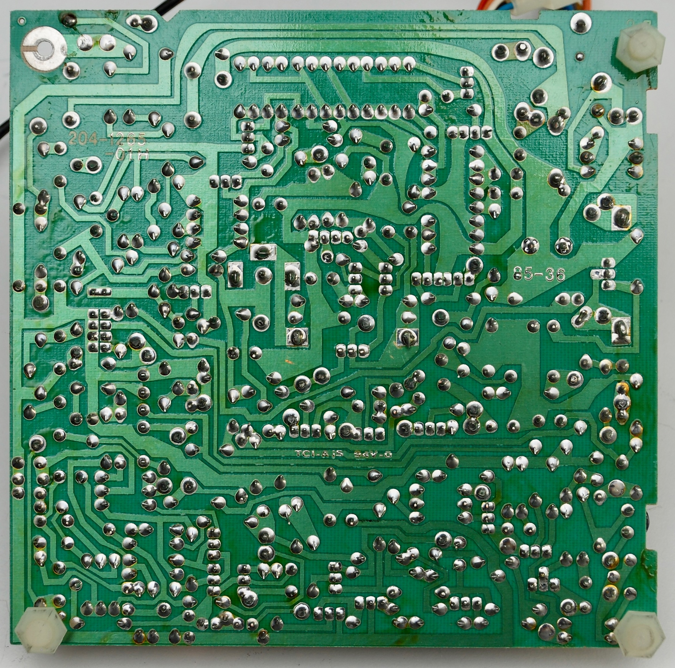
Capacitors List

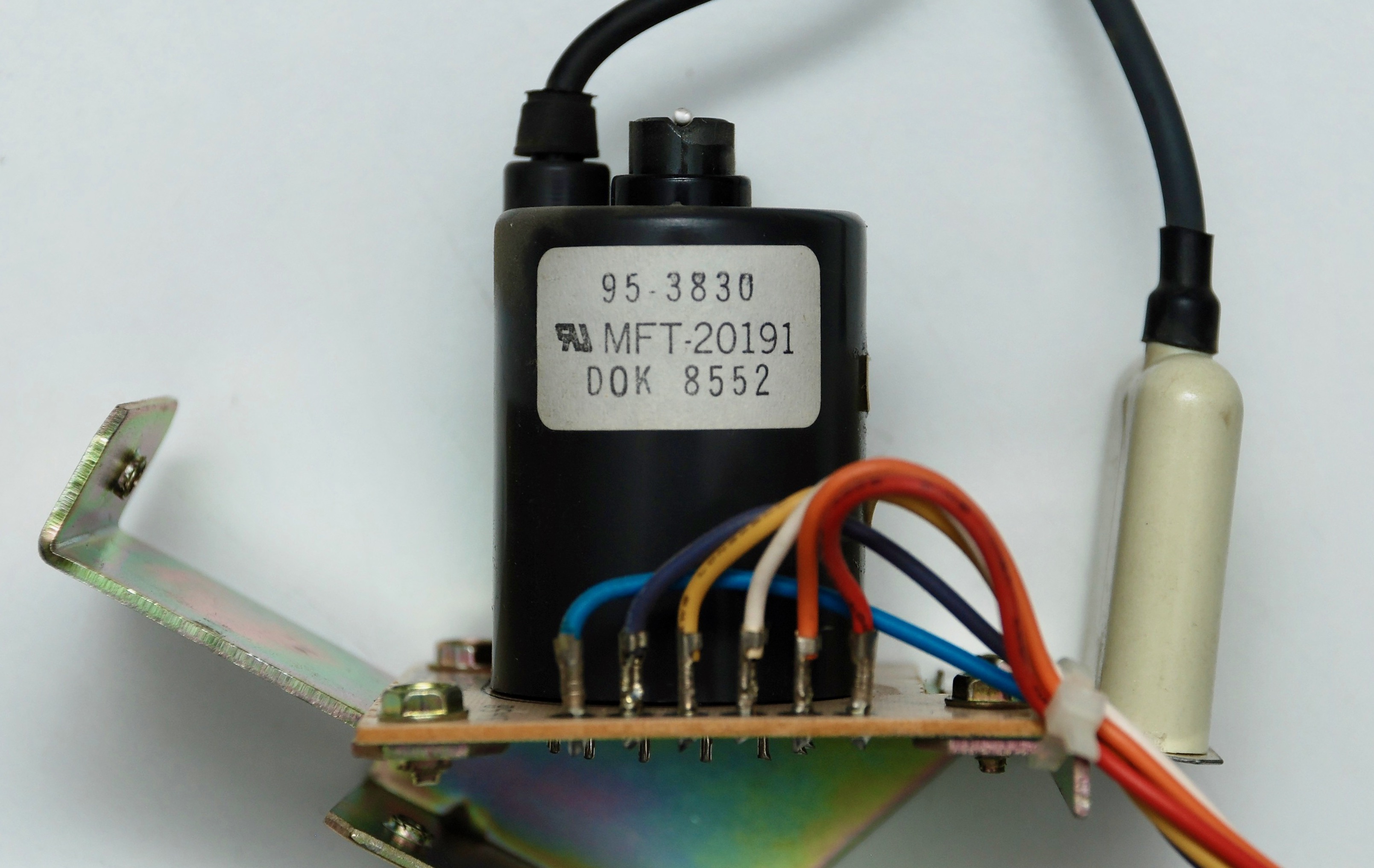
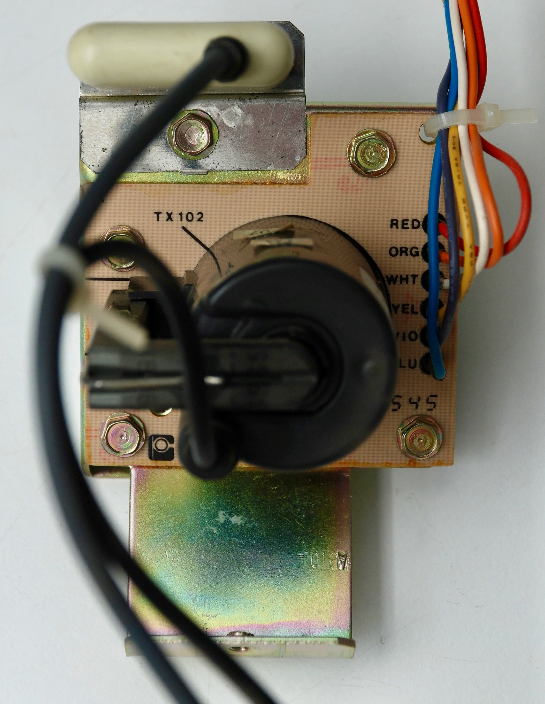
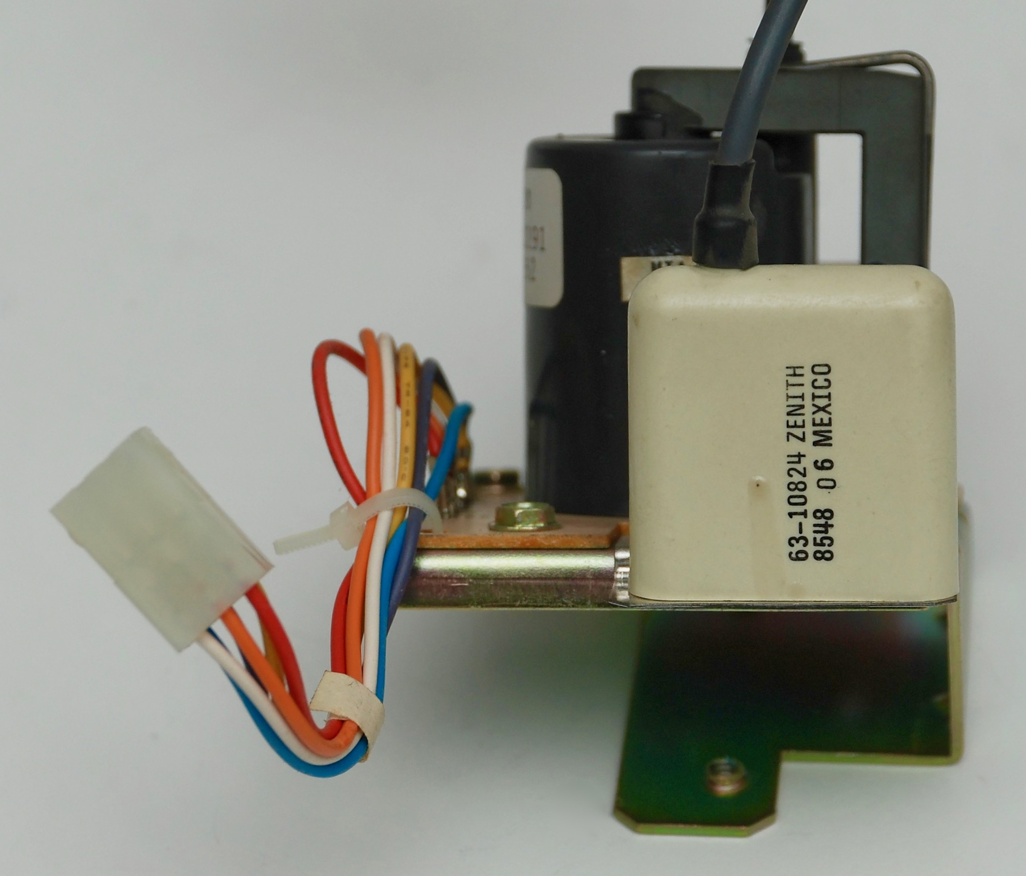
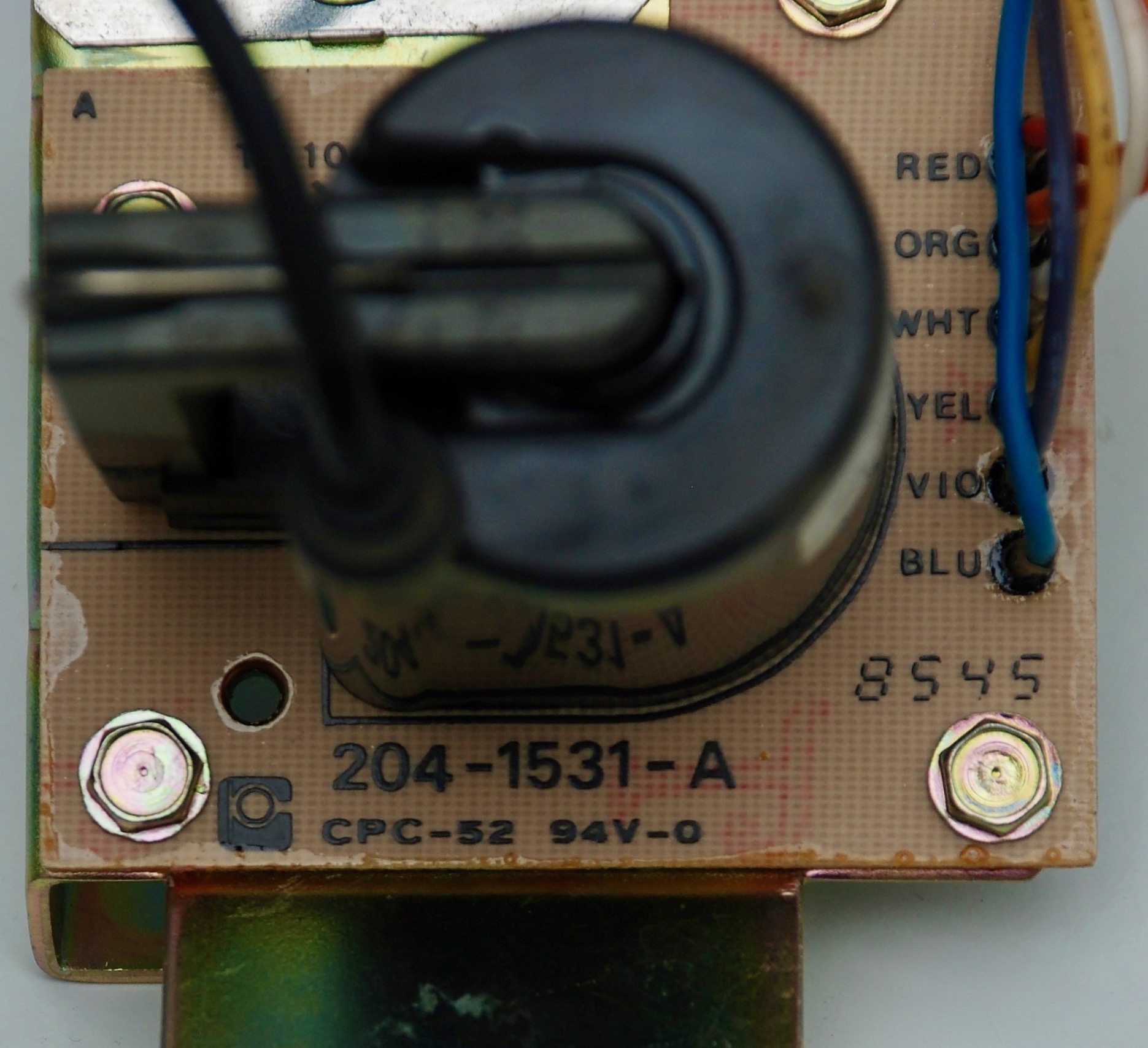
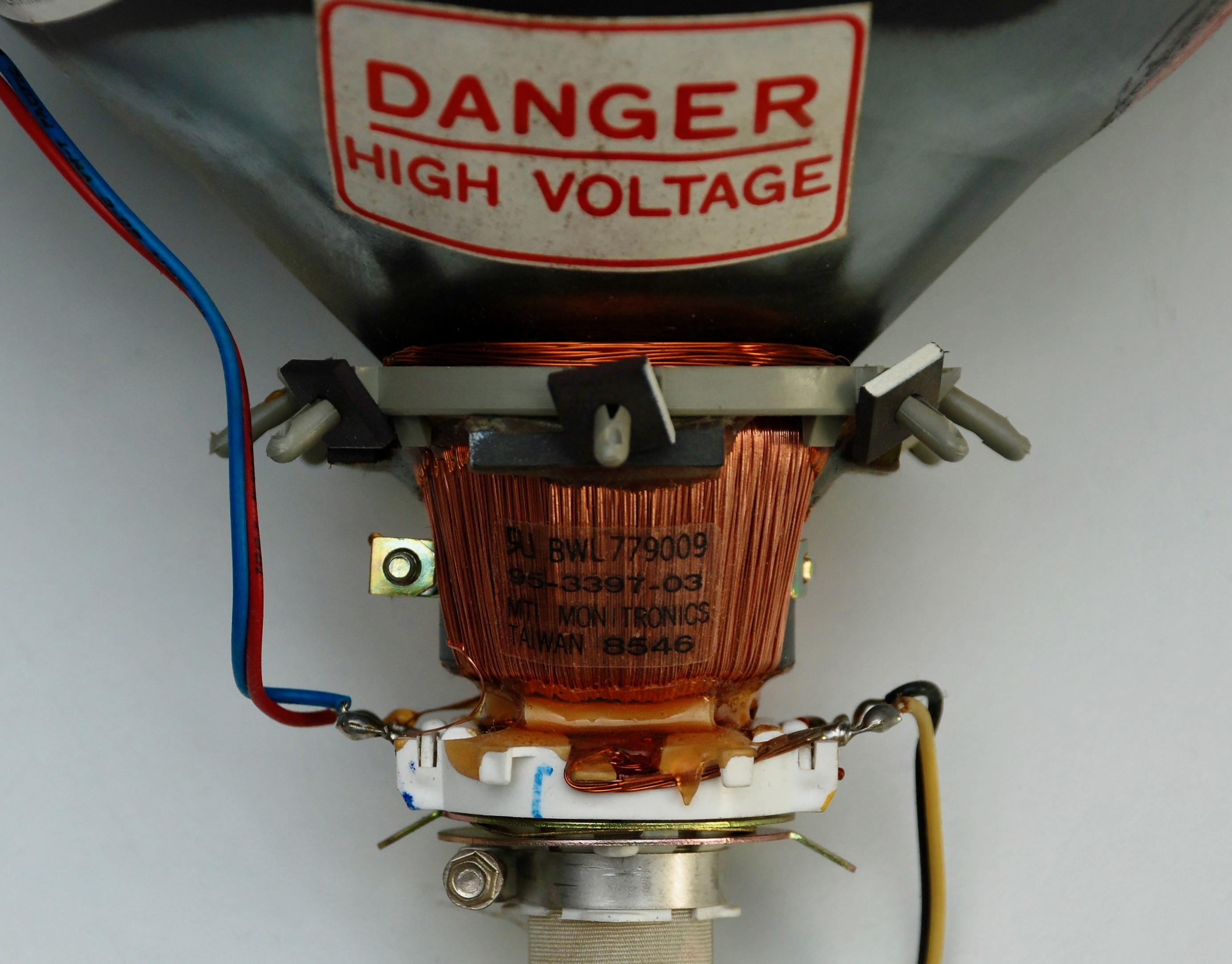
Flyback Transformer
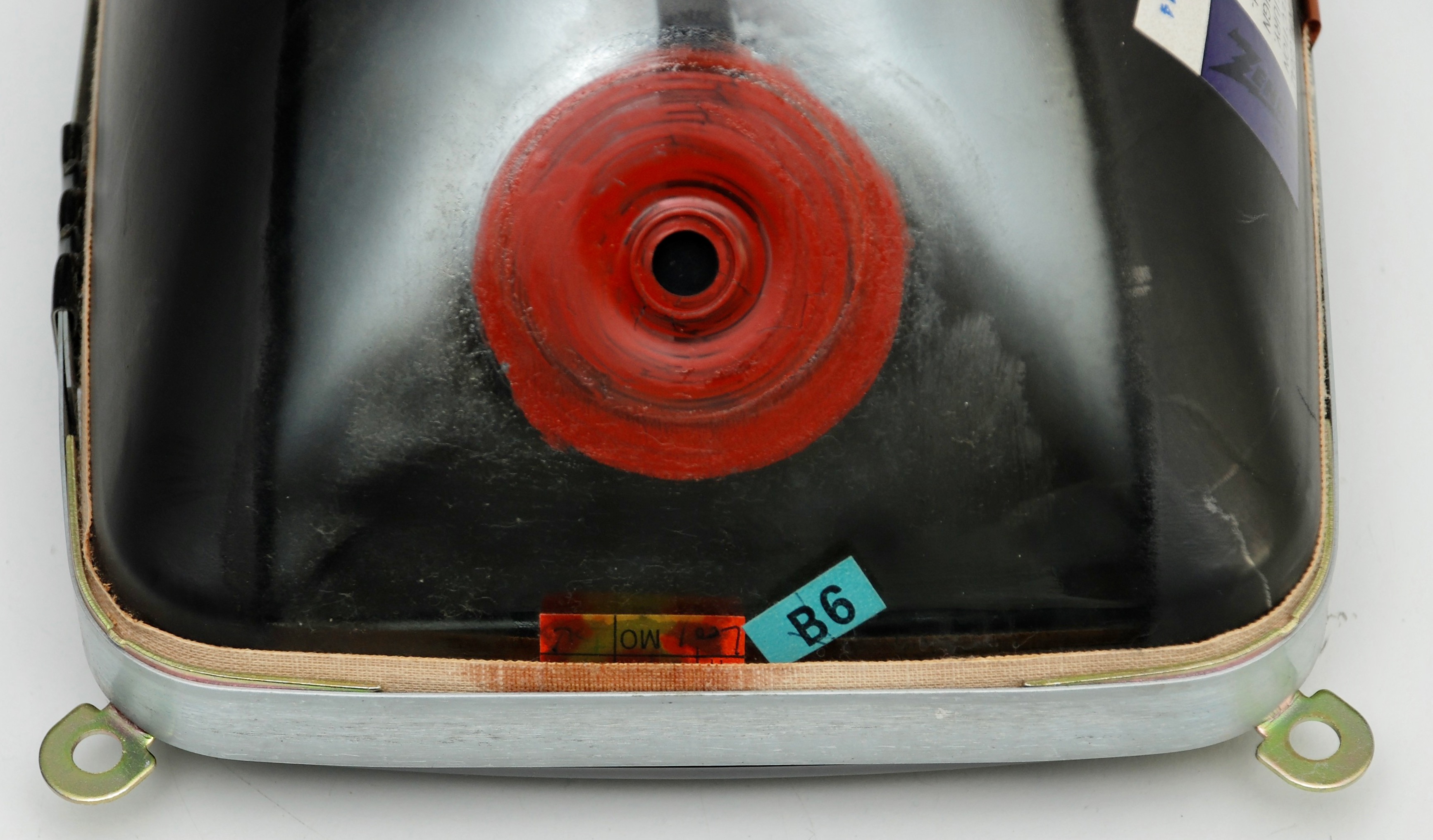
CRT Board
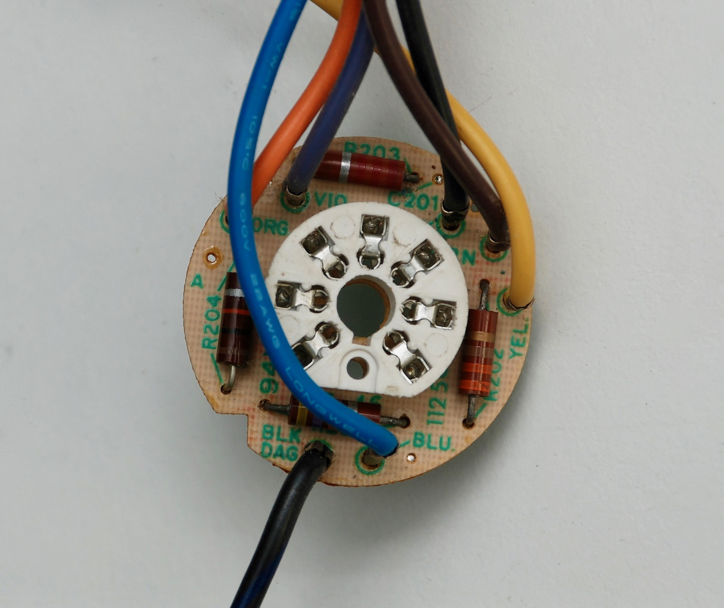
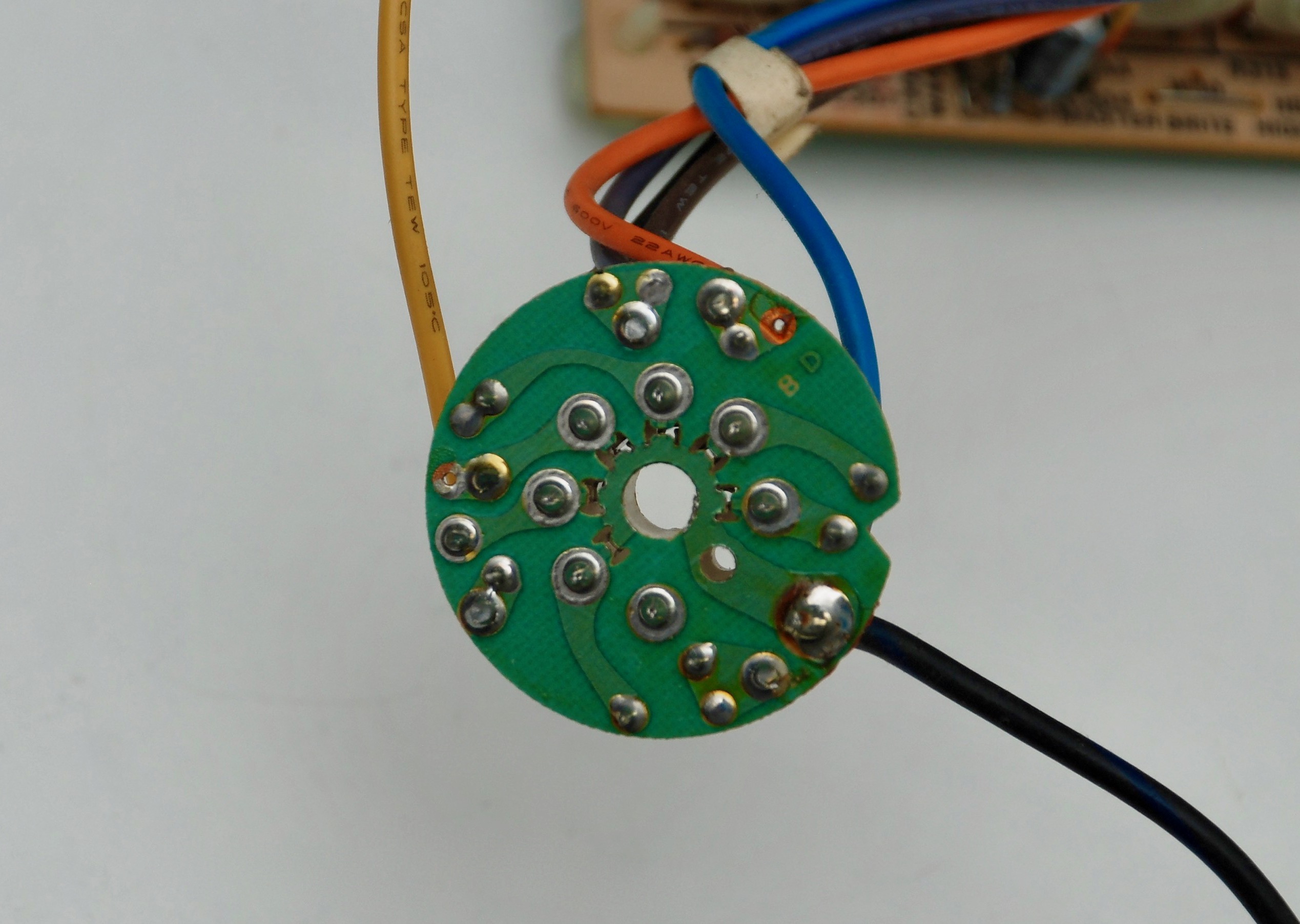
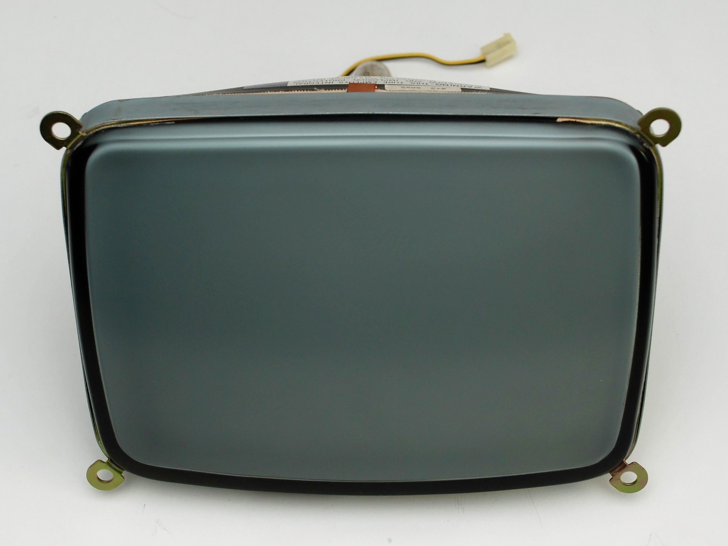
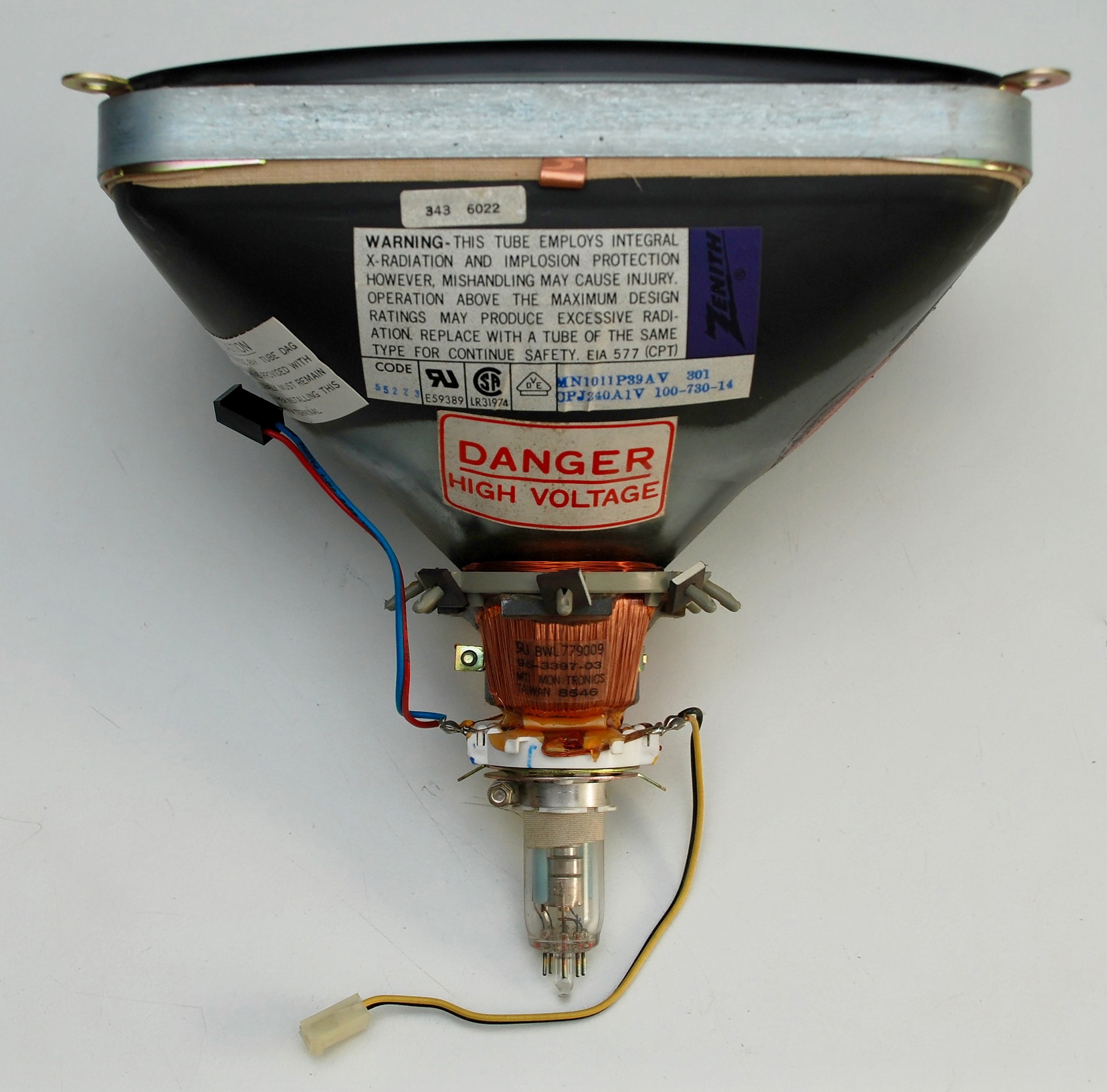
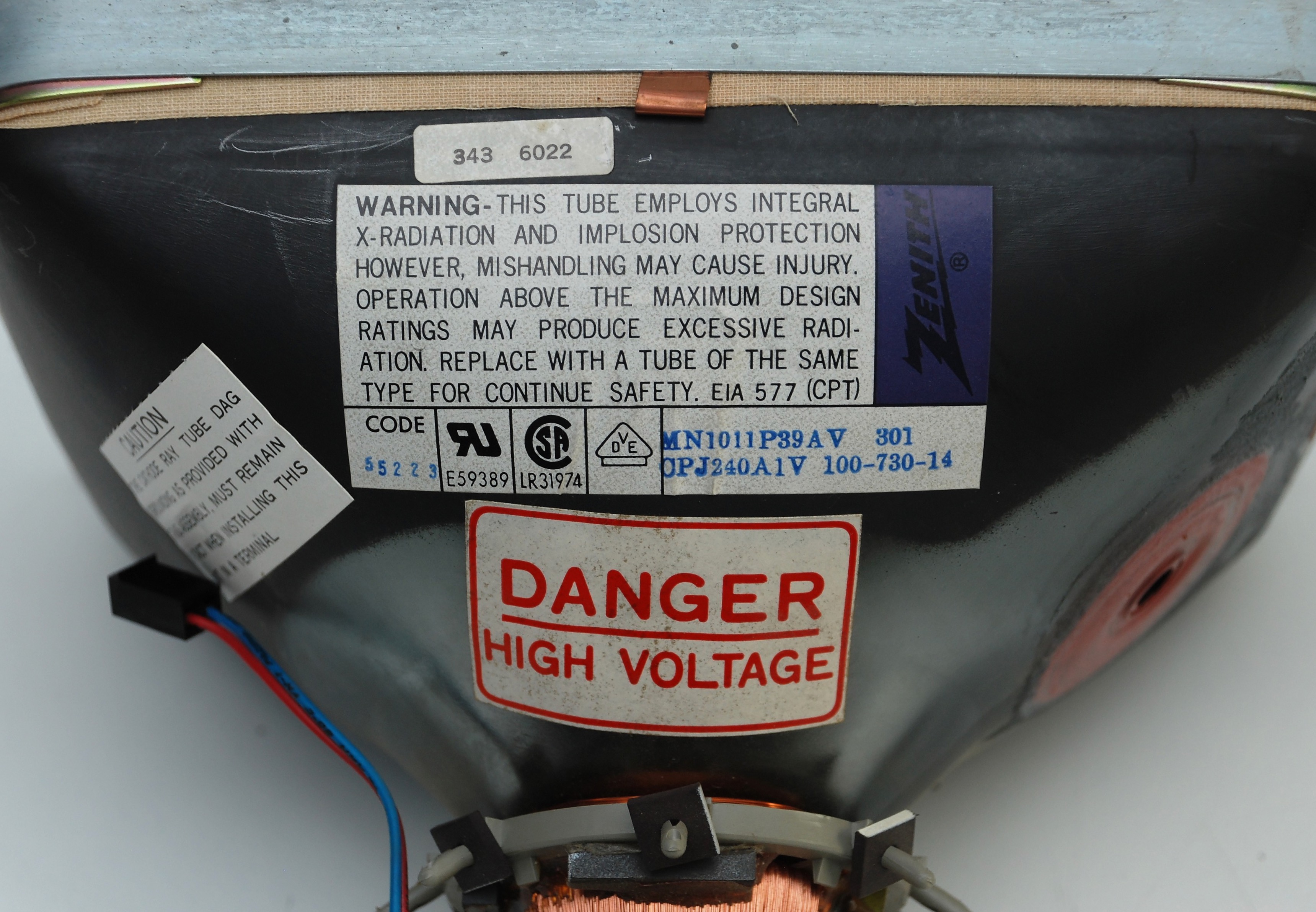
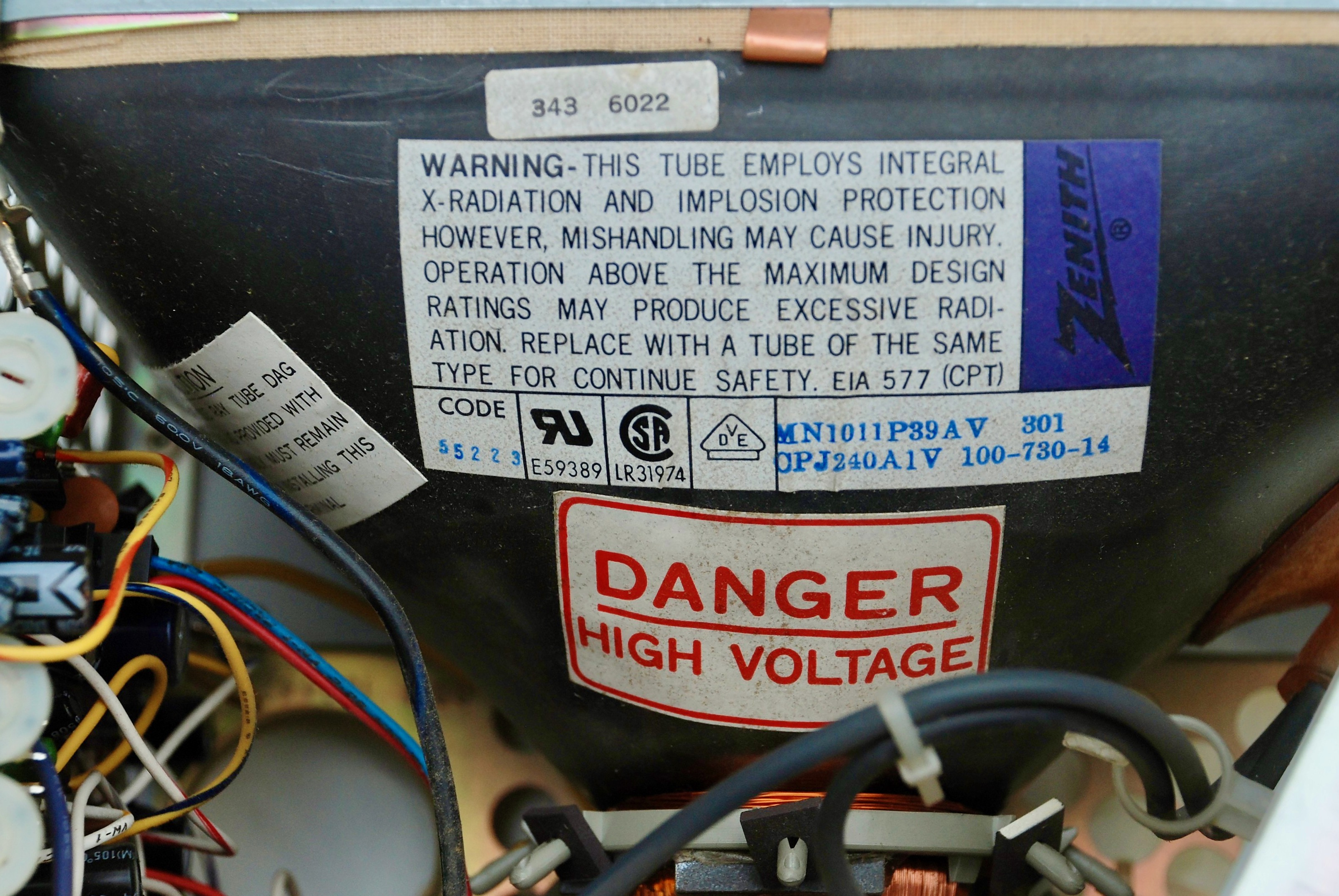
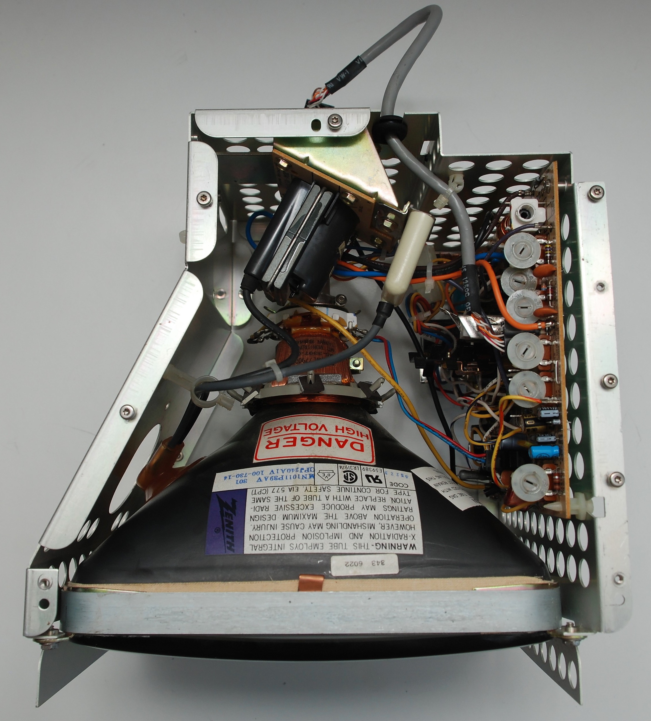
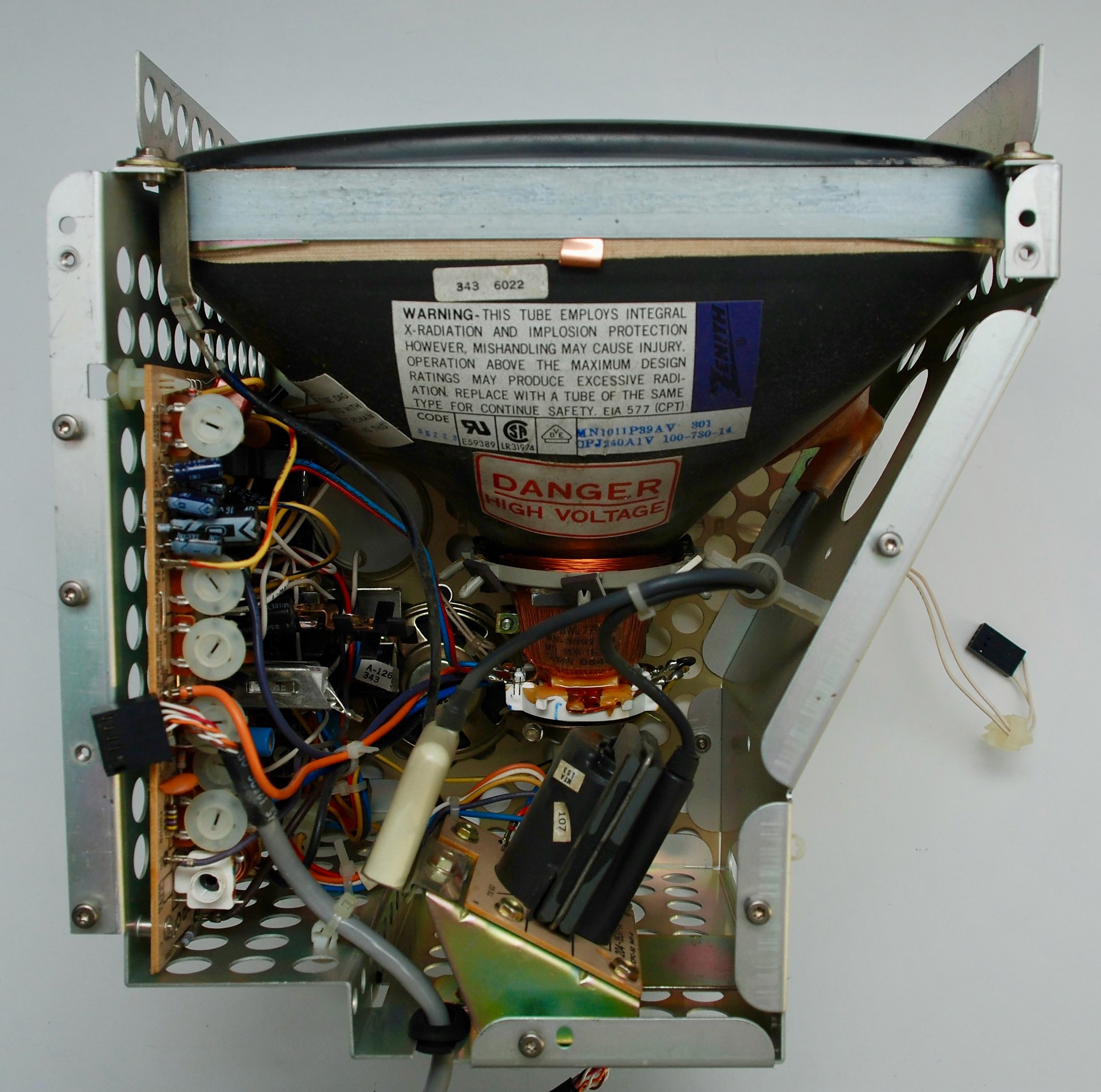
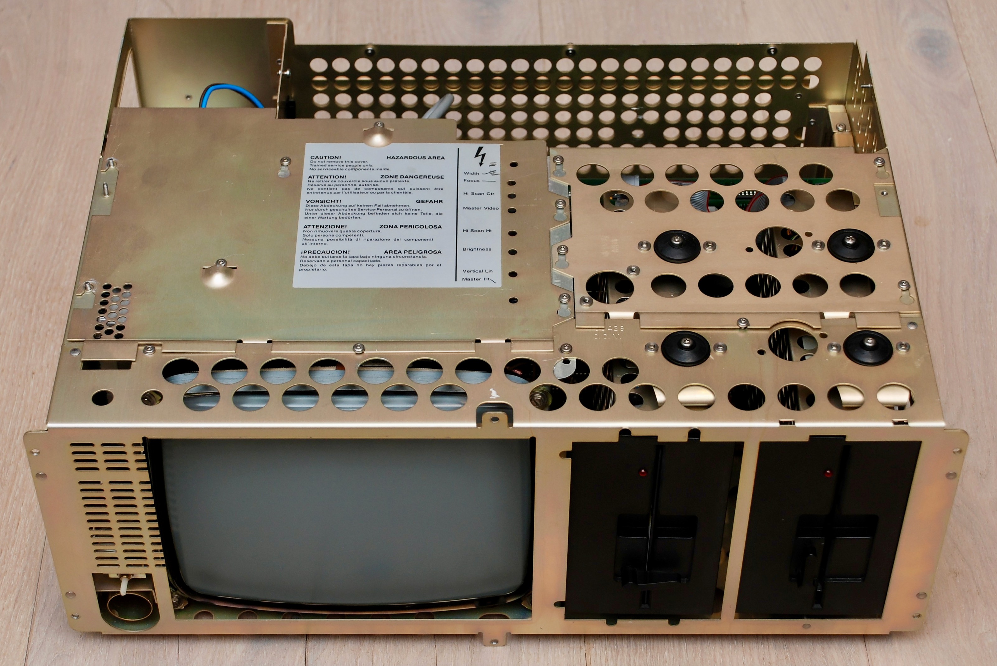
CRT
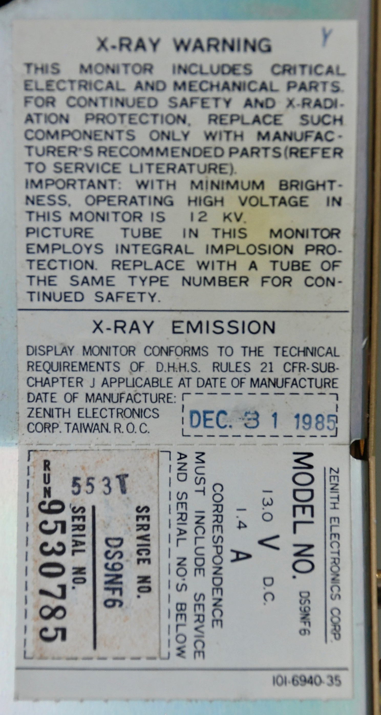
Zenith MN1011P39AV

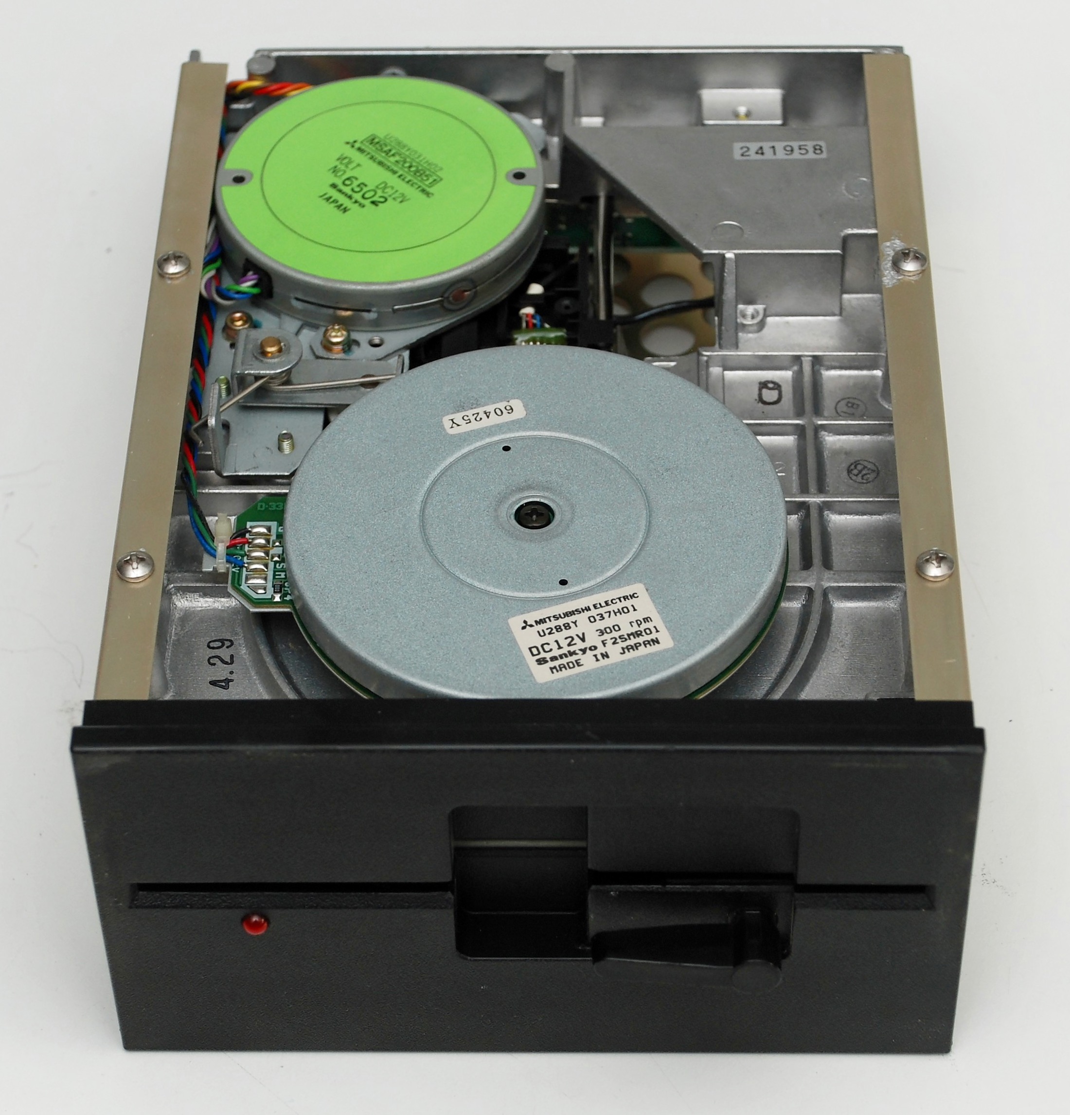
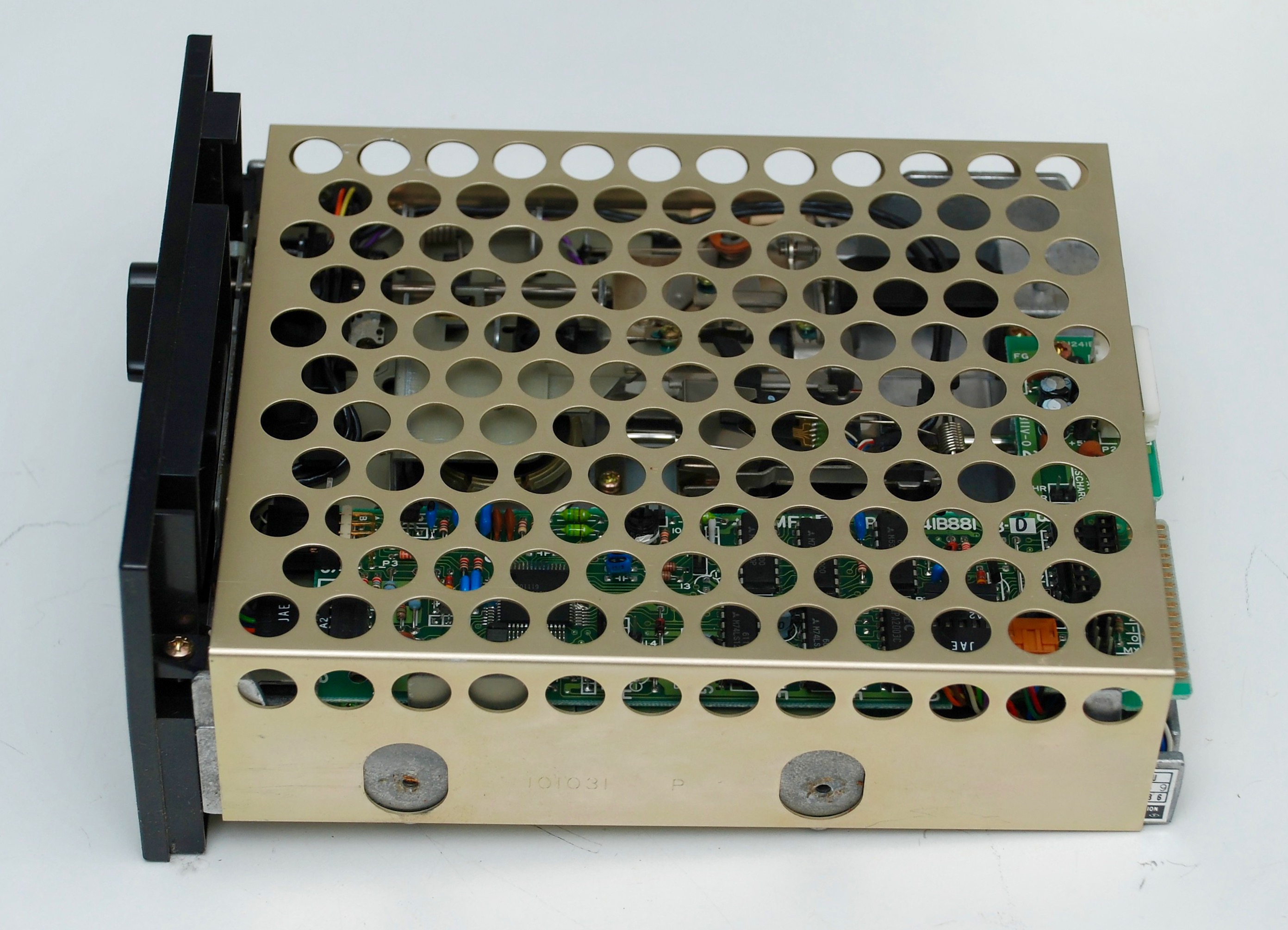
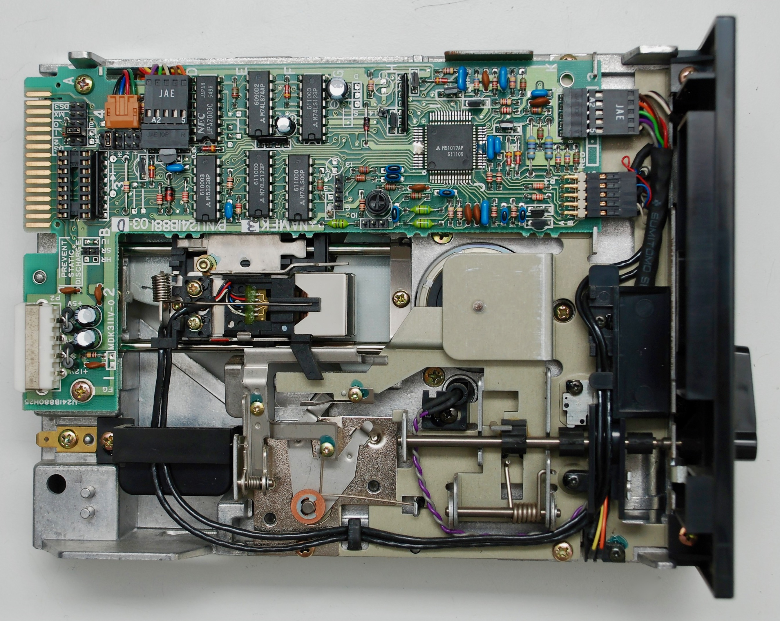
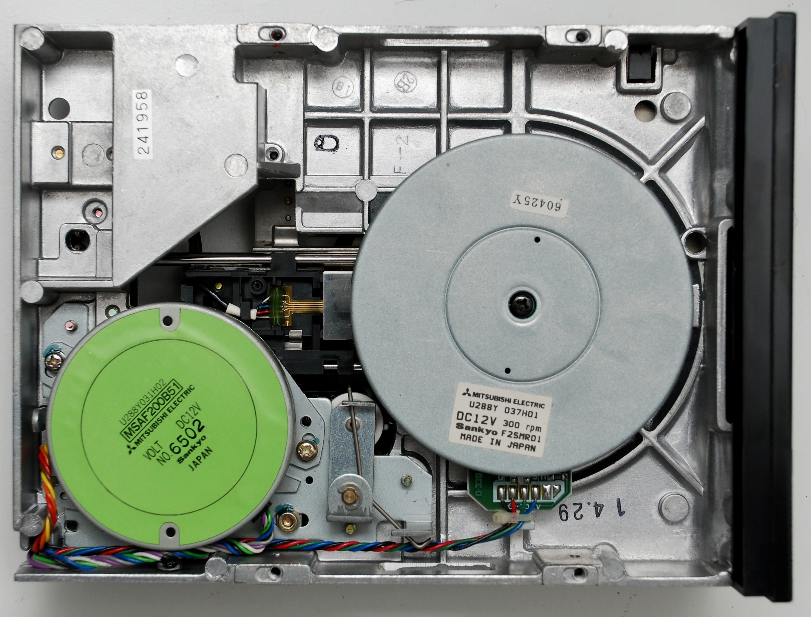
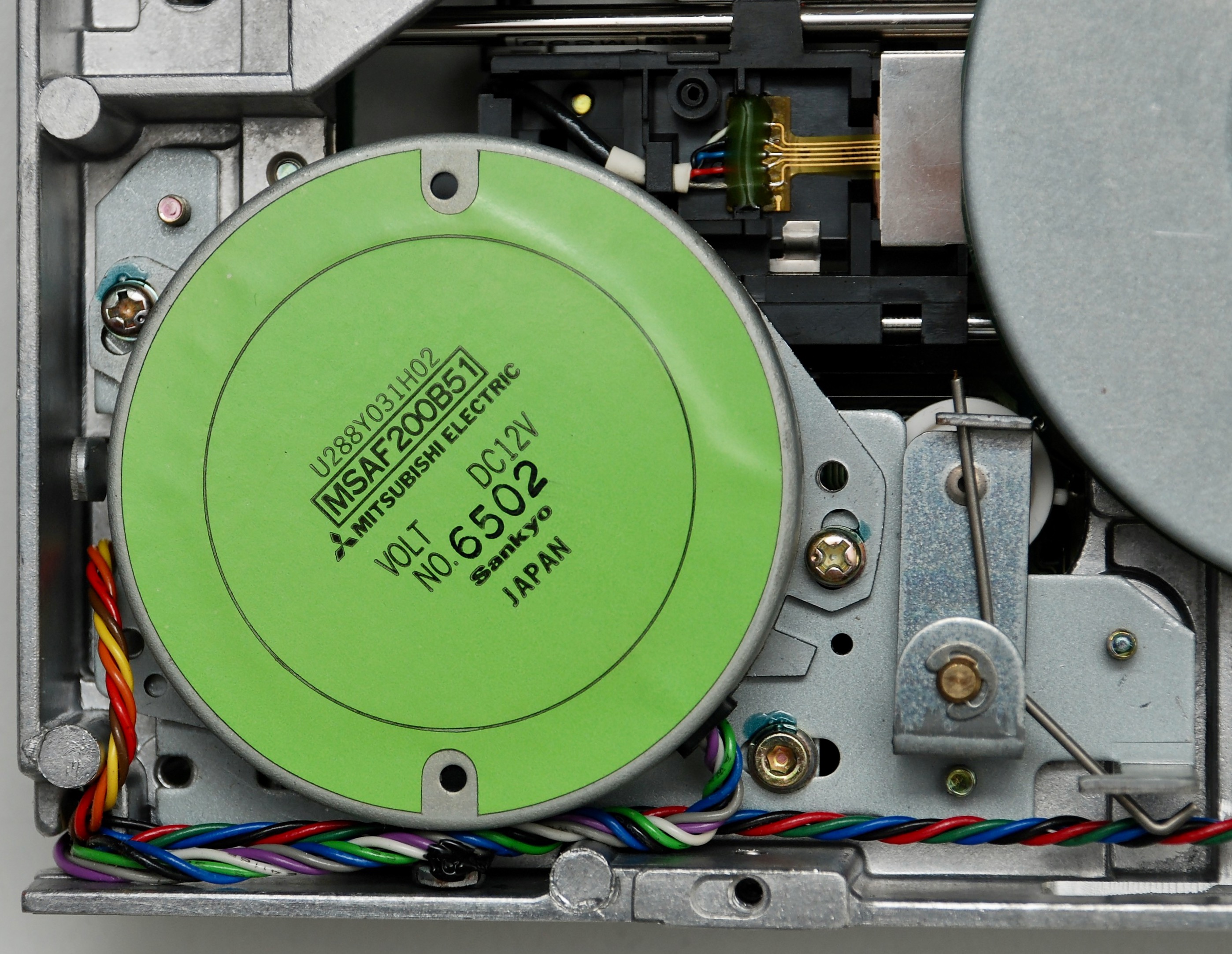
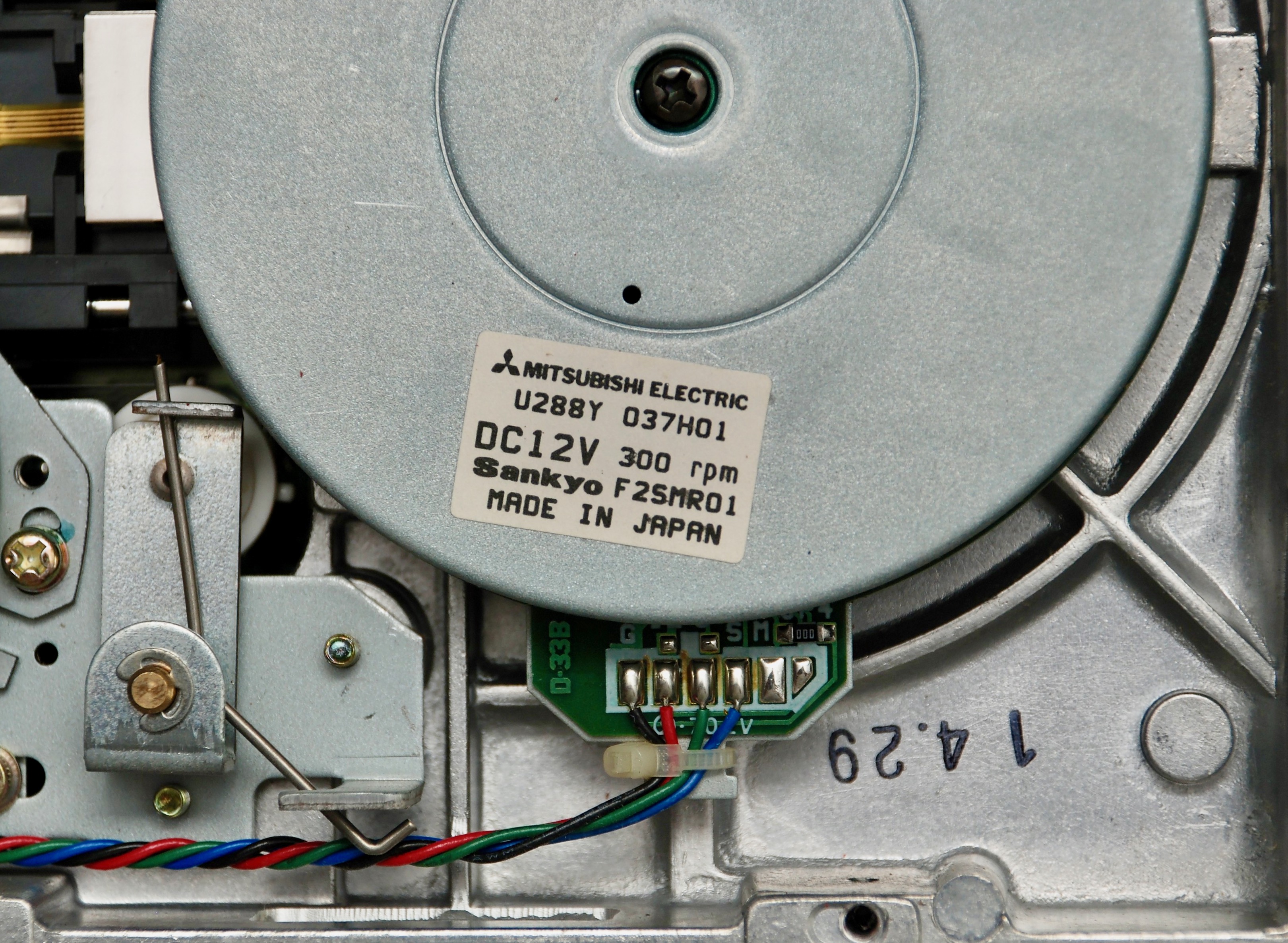
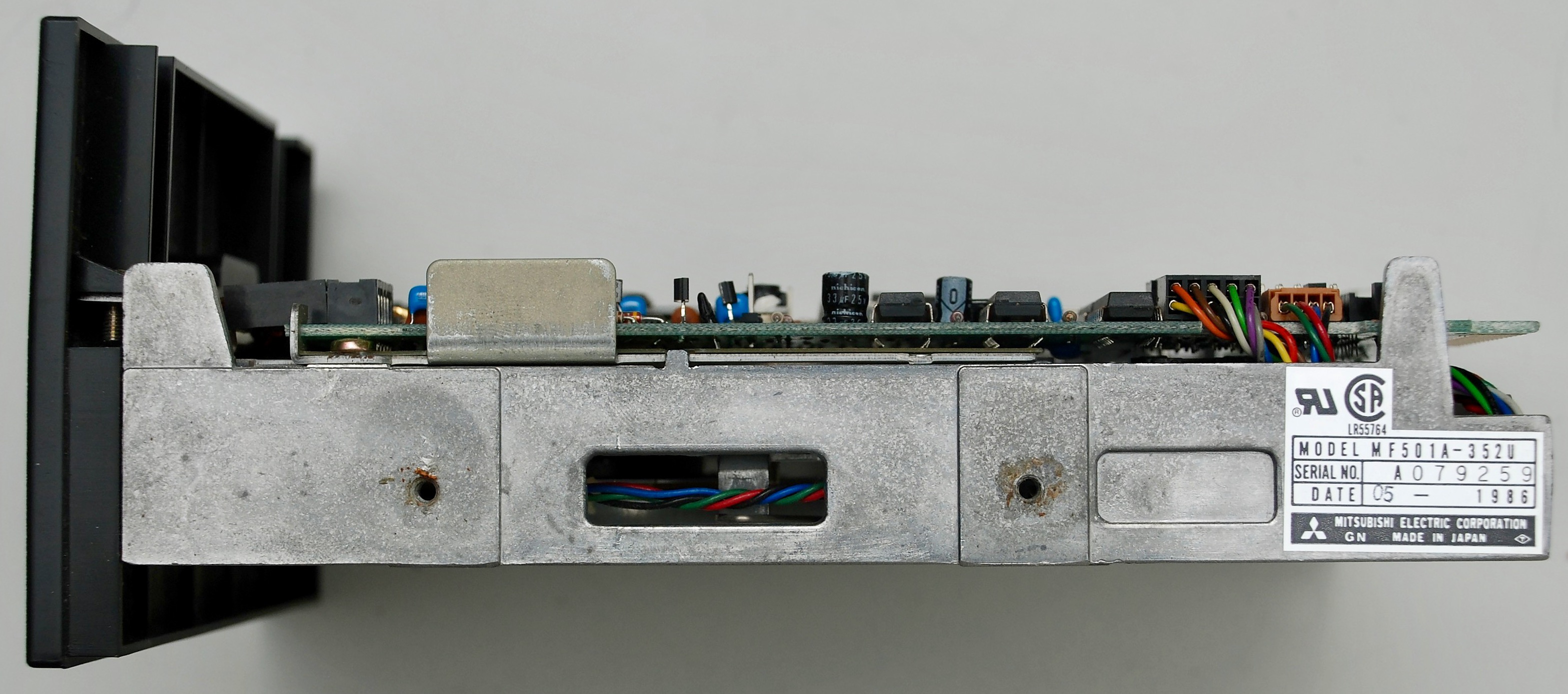
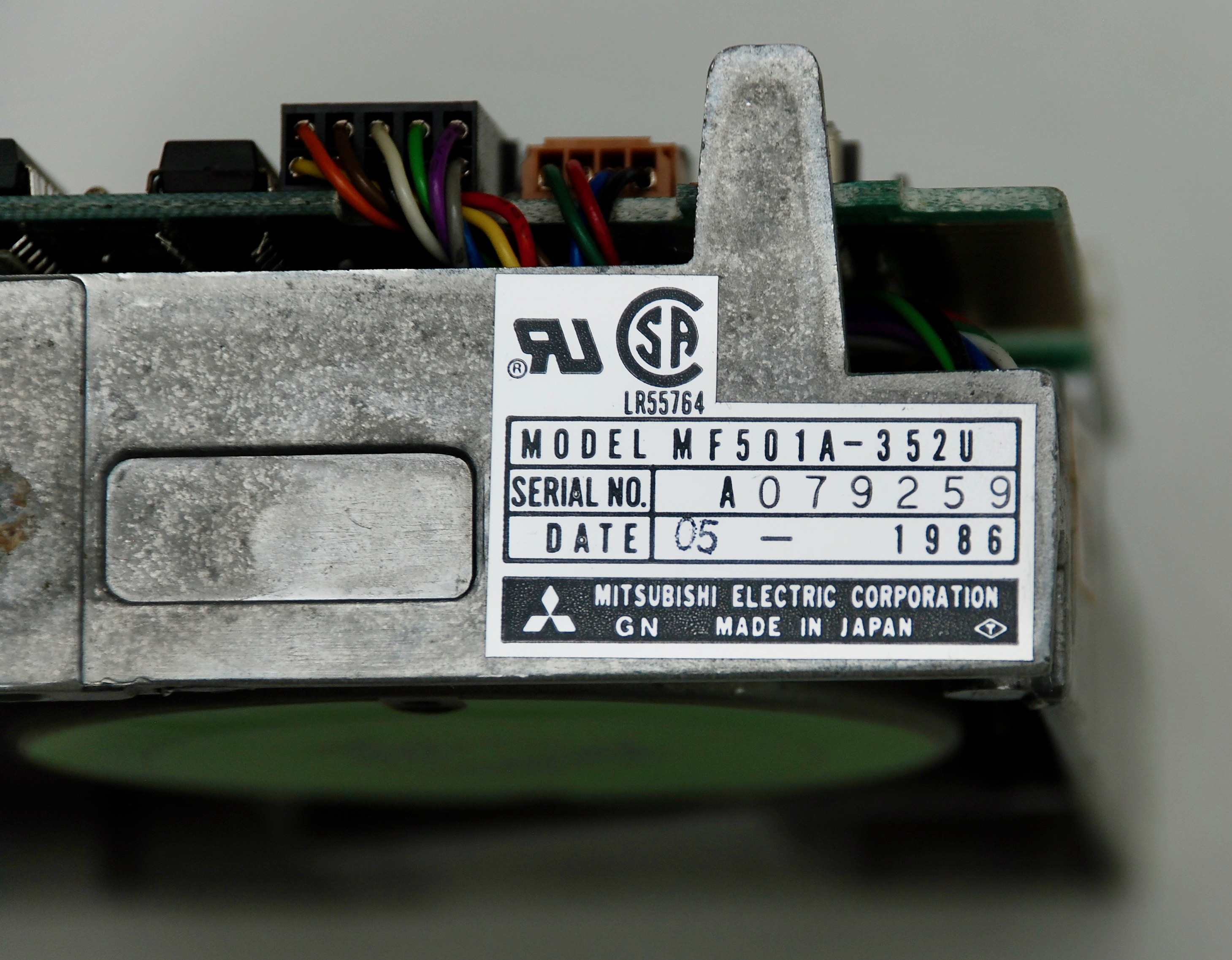
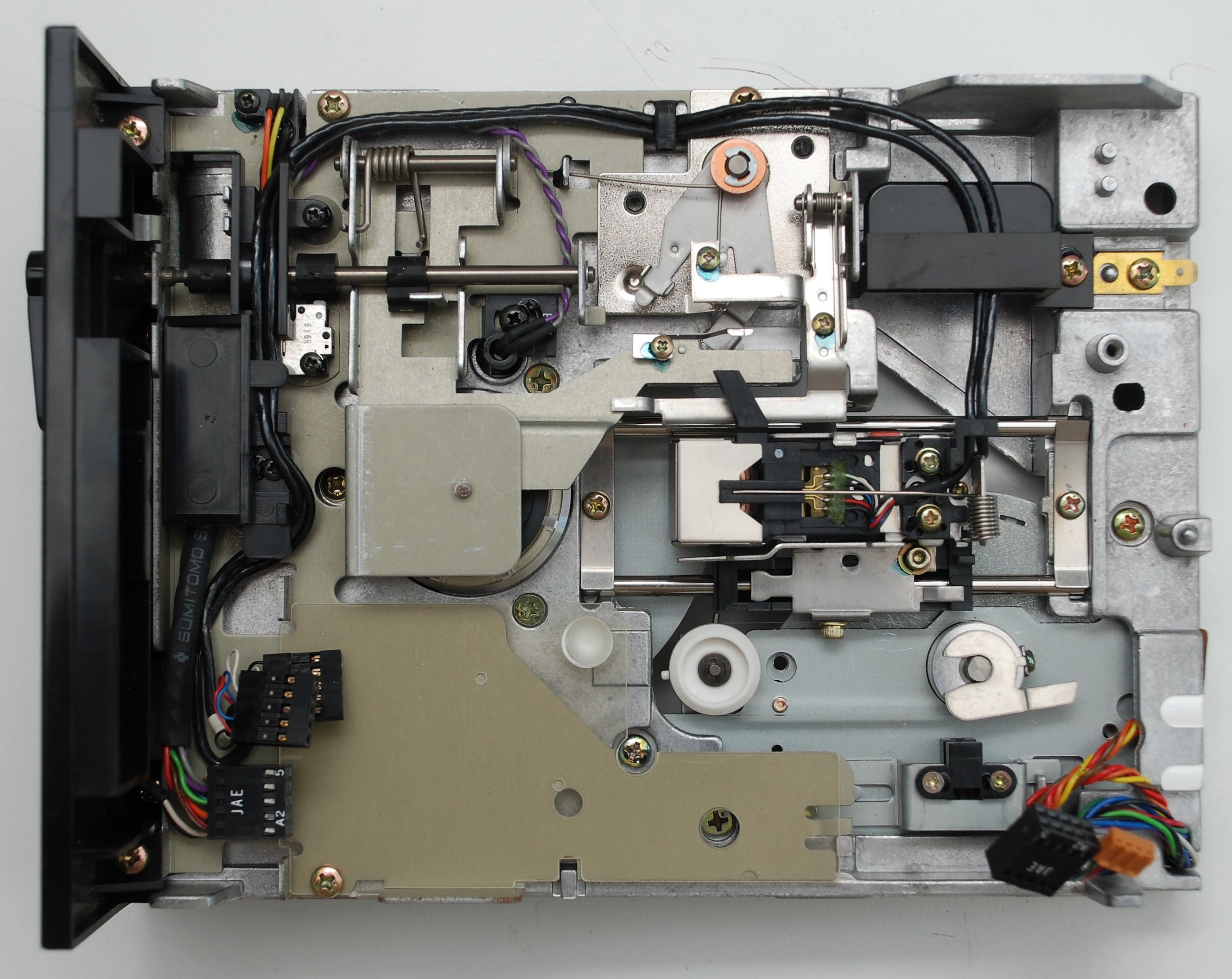
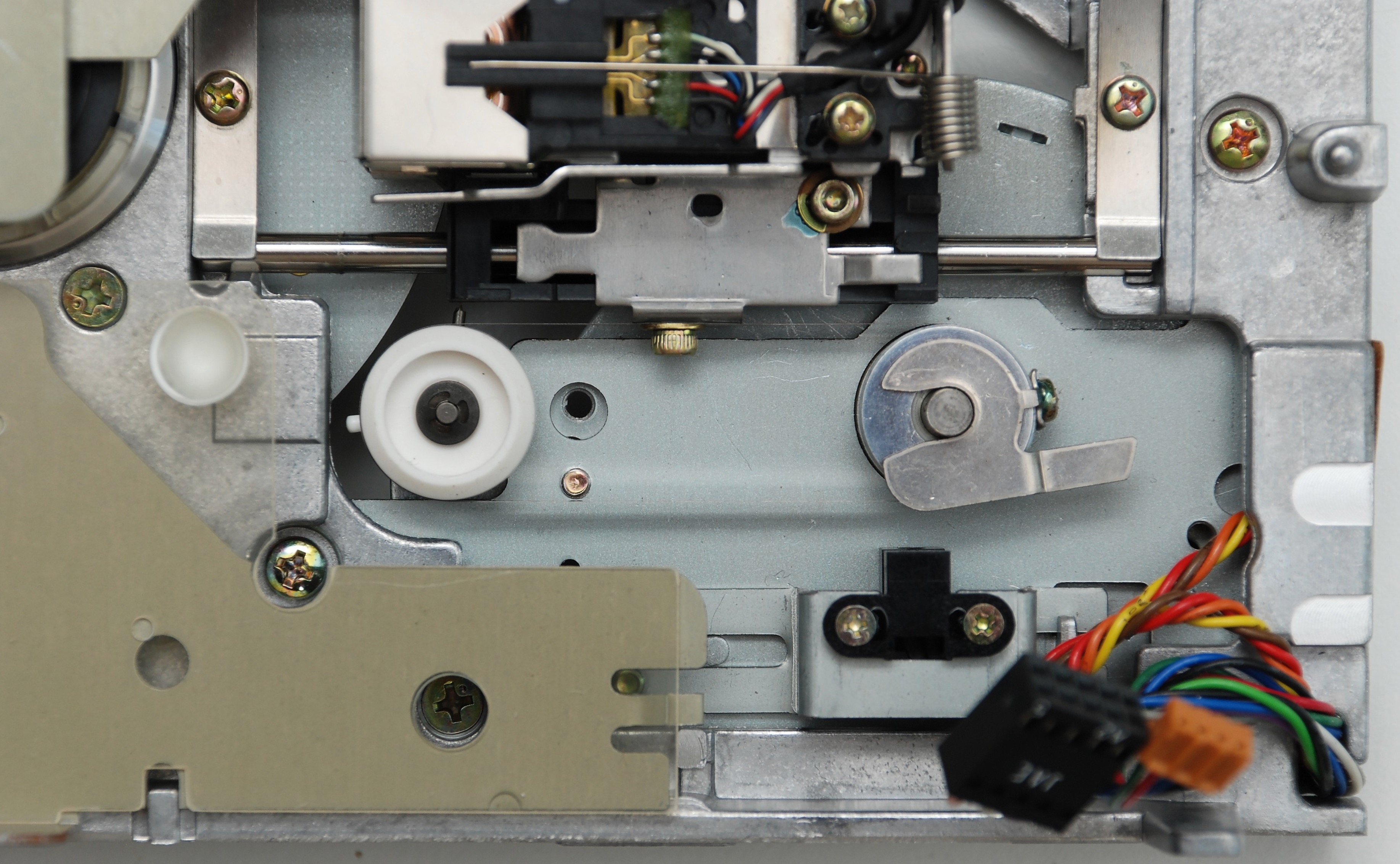
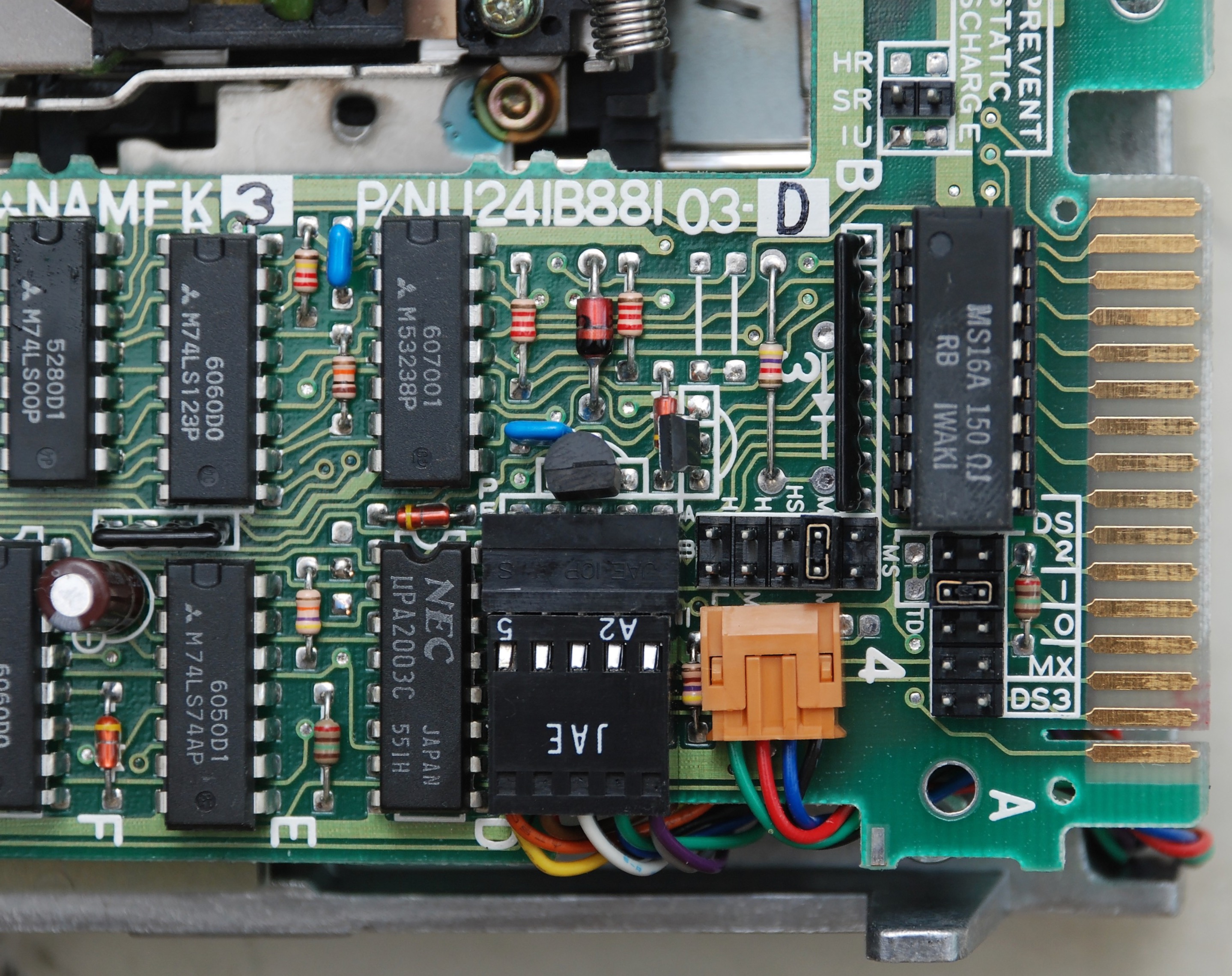
Floppy Disk Drive
Mitsubishi MF501A-352U

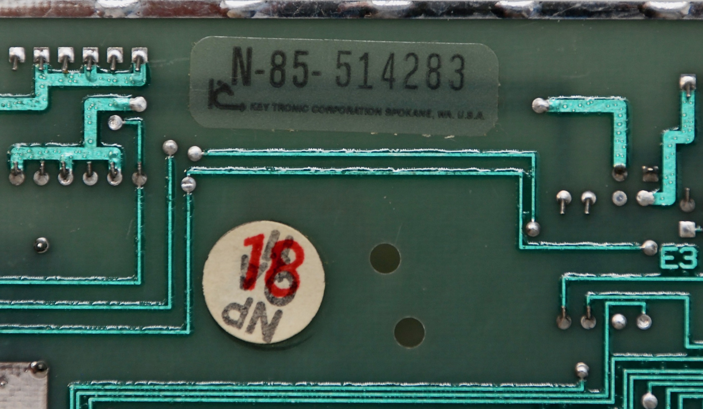
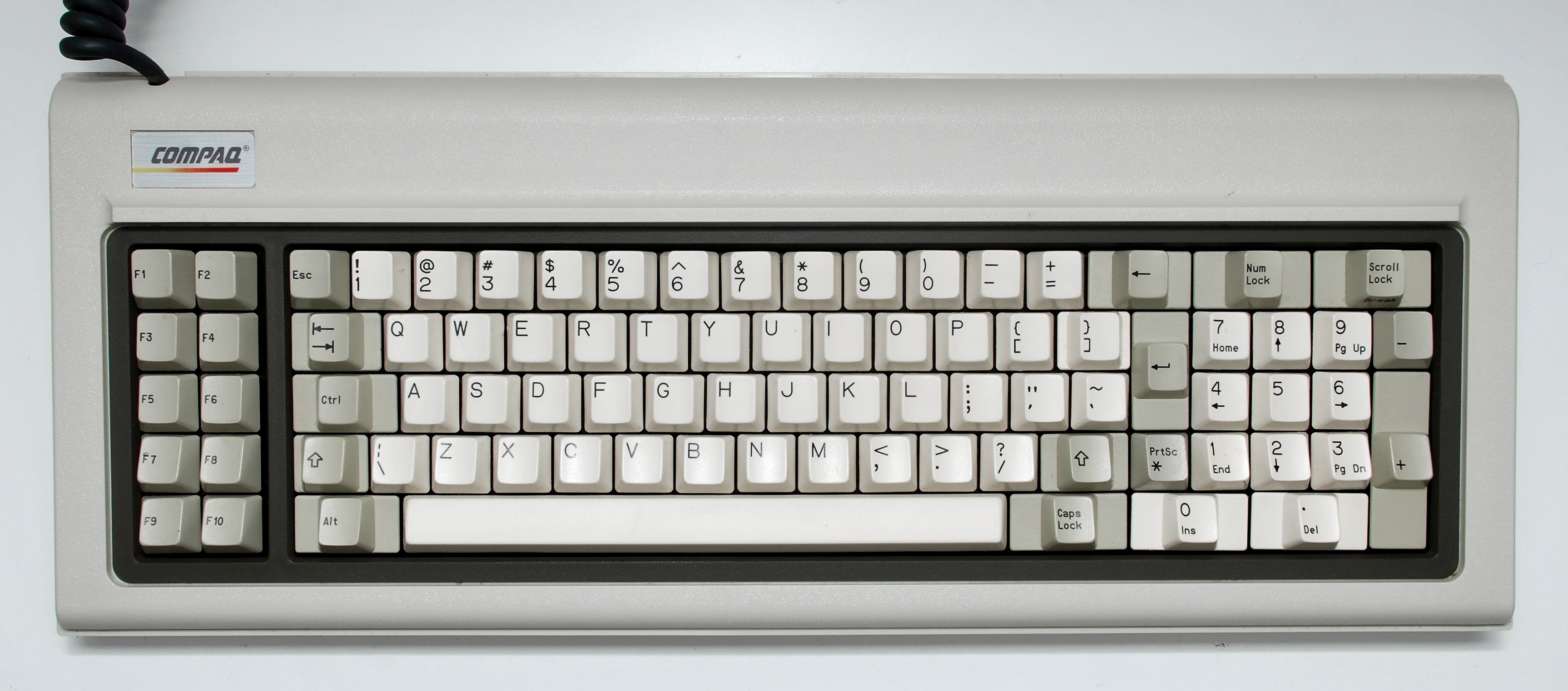
Keyboard


Reassembly
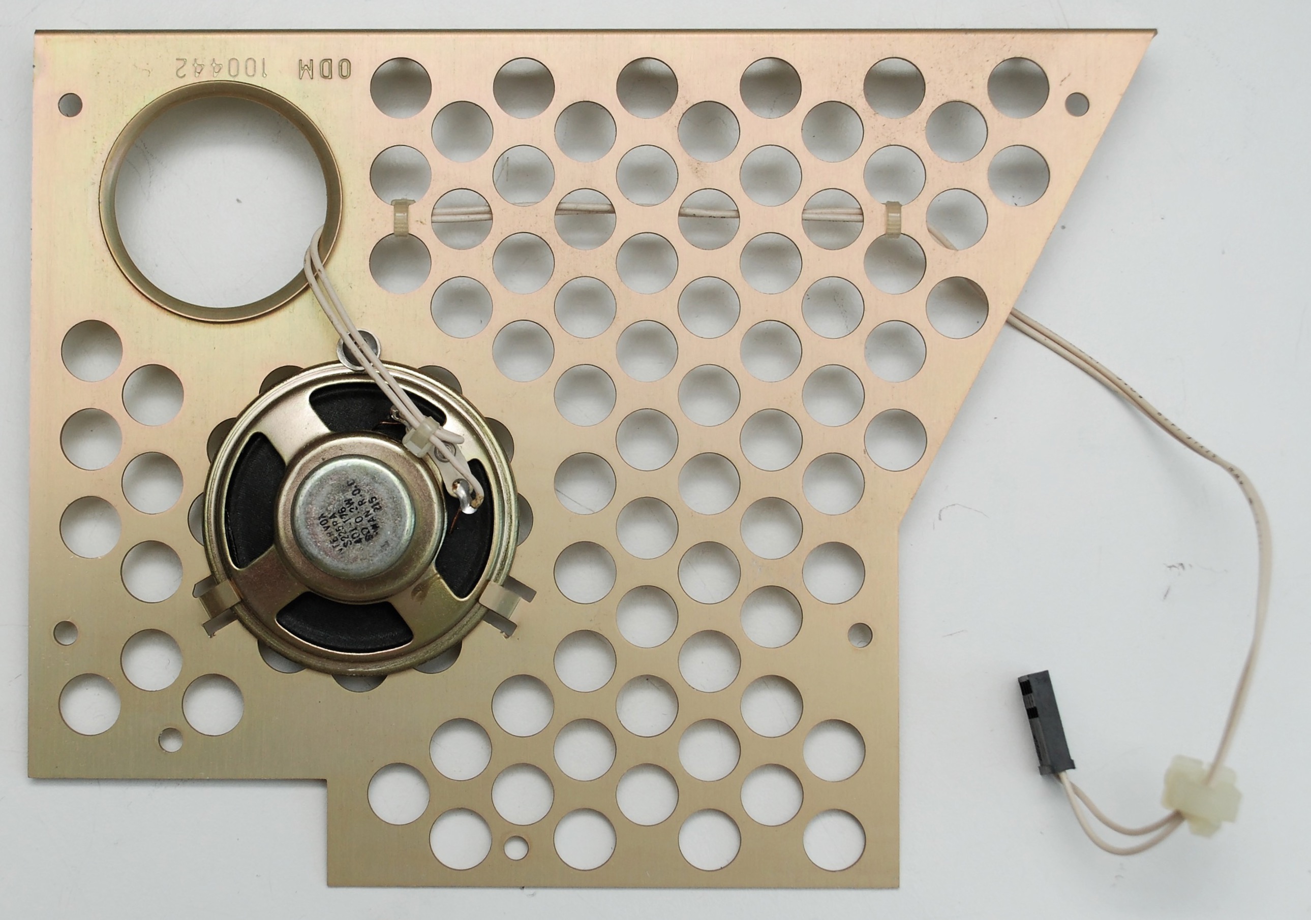
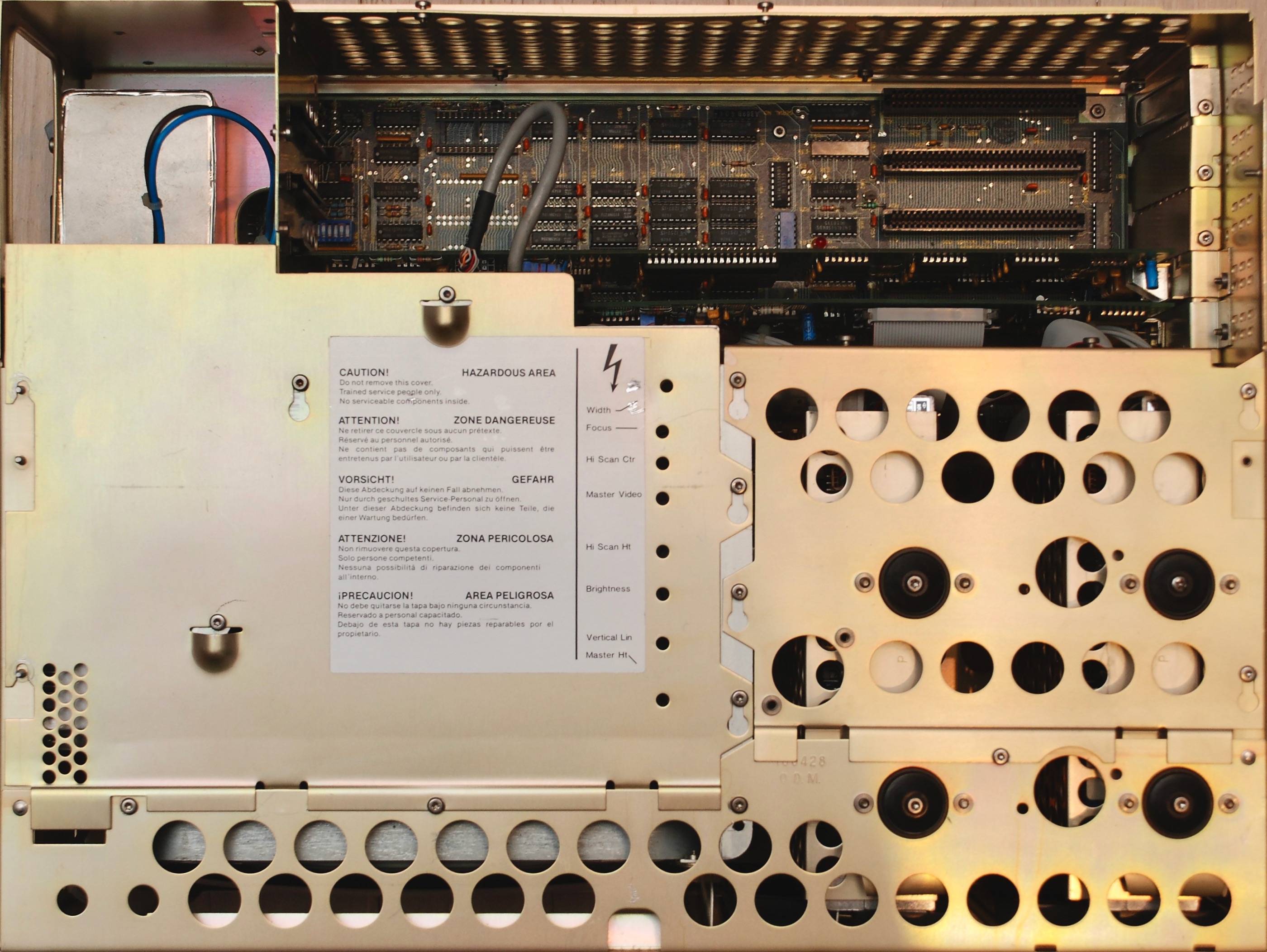
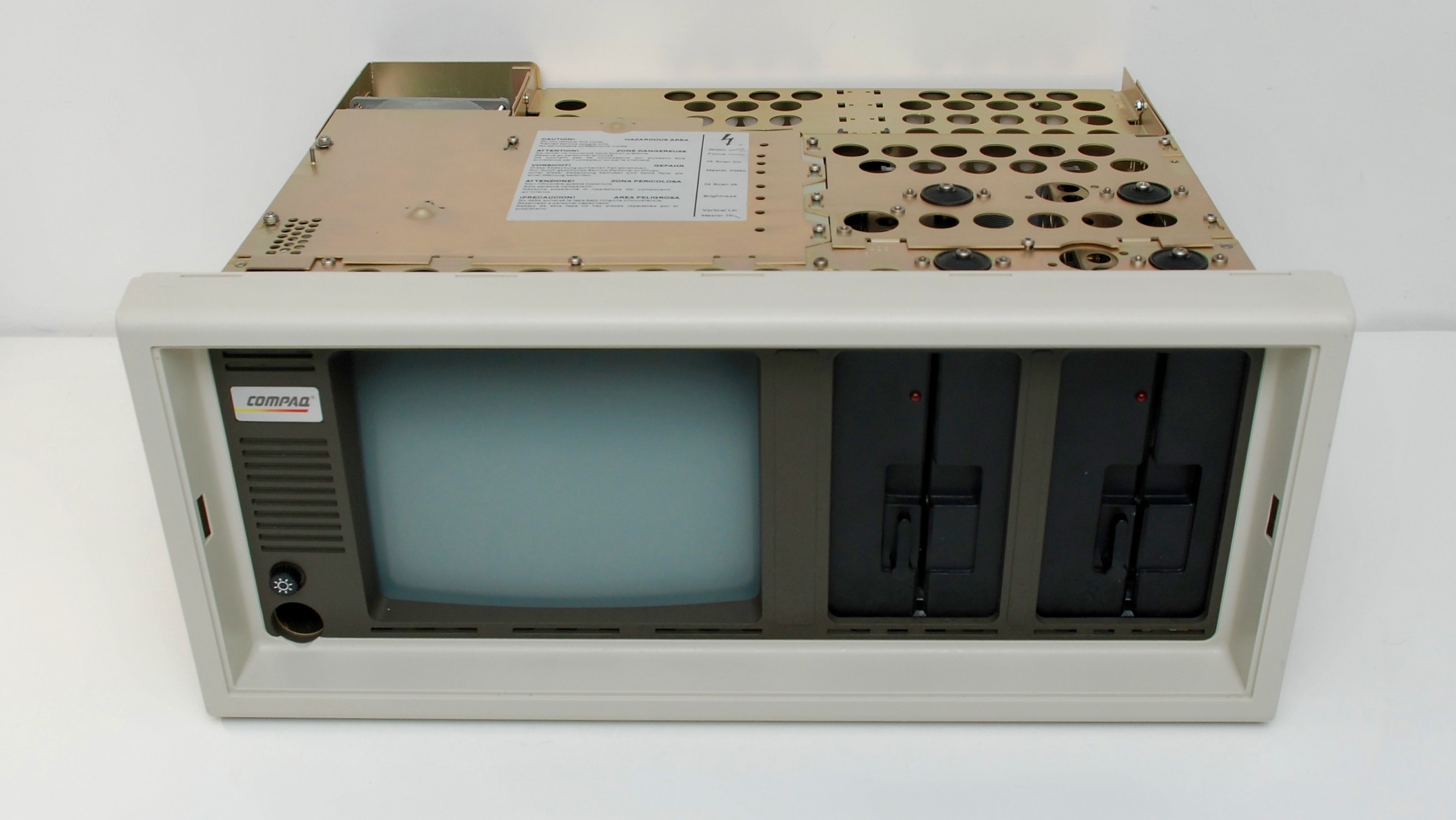
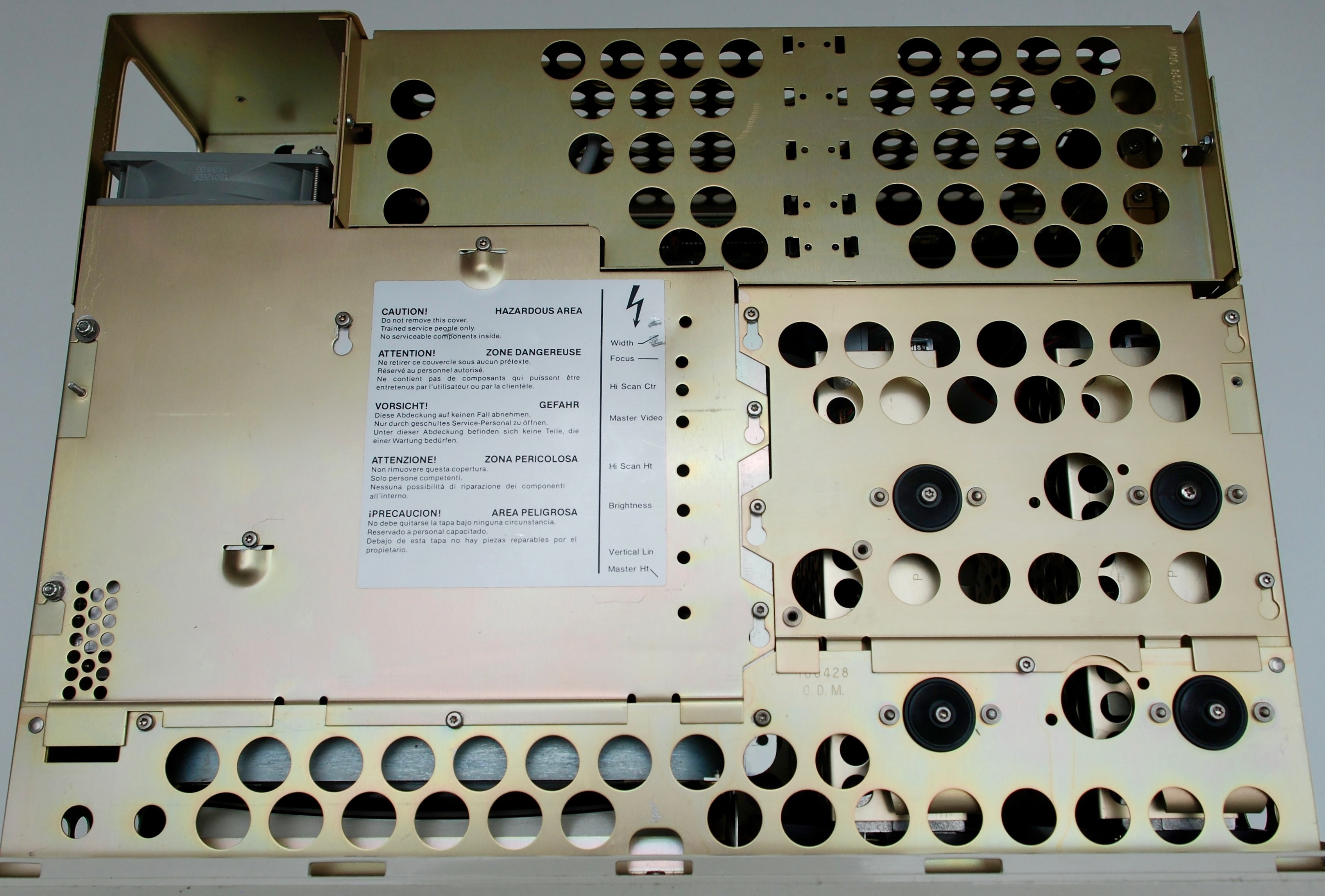
Display Complex
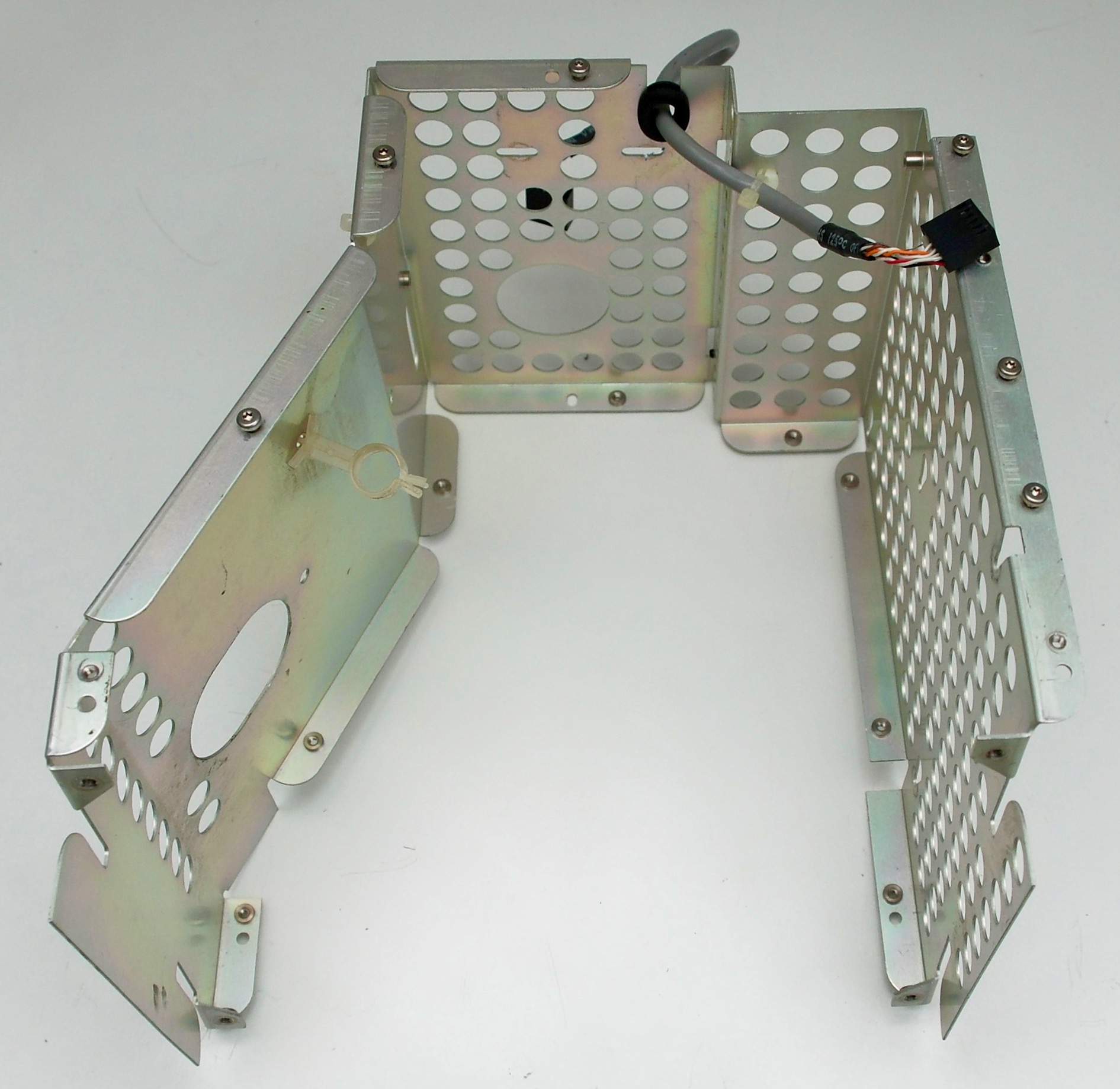
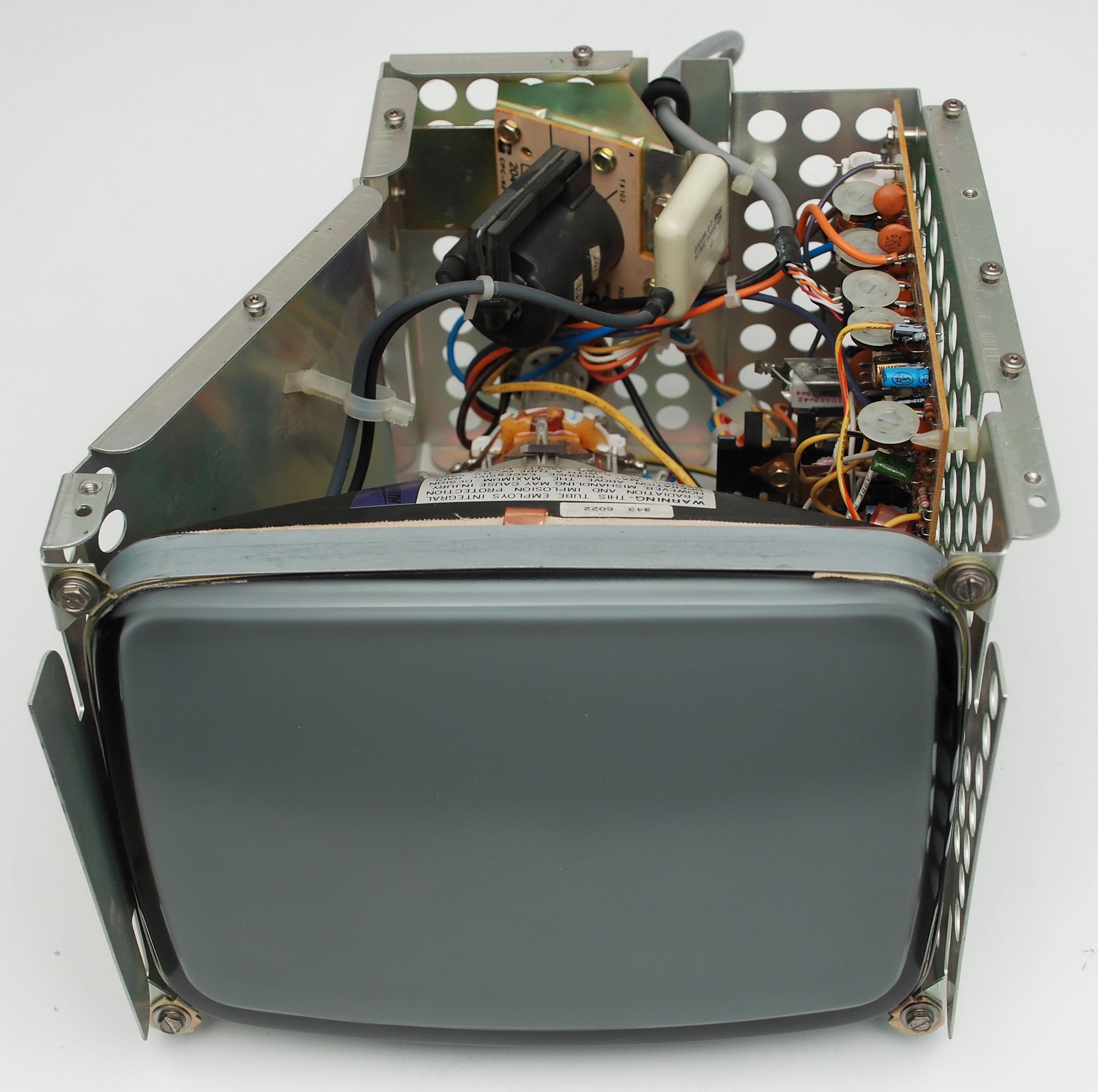
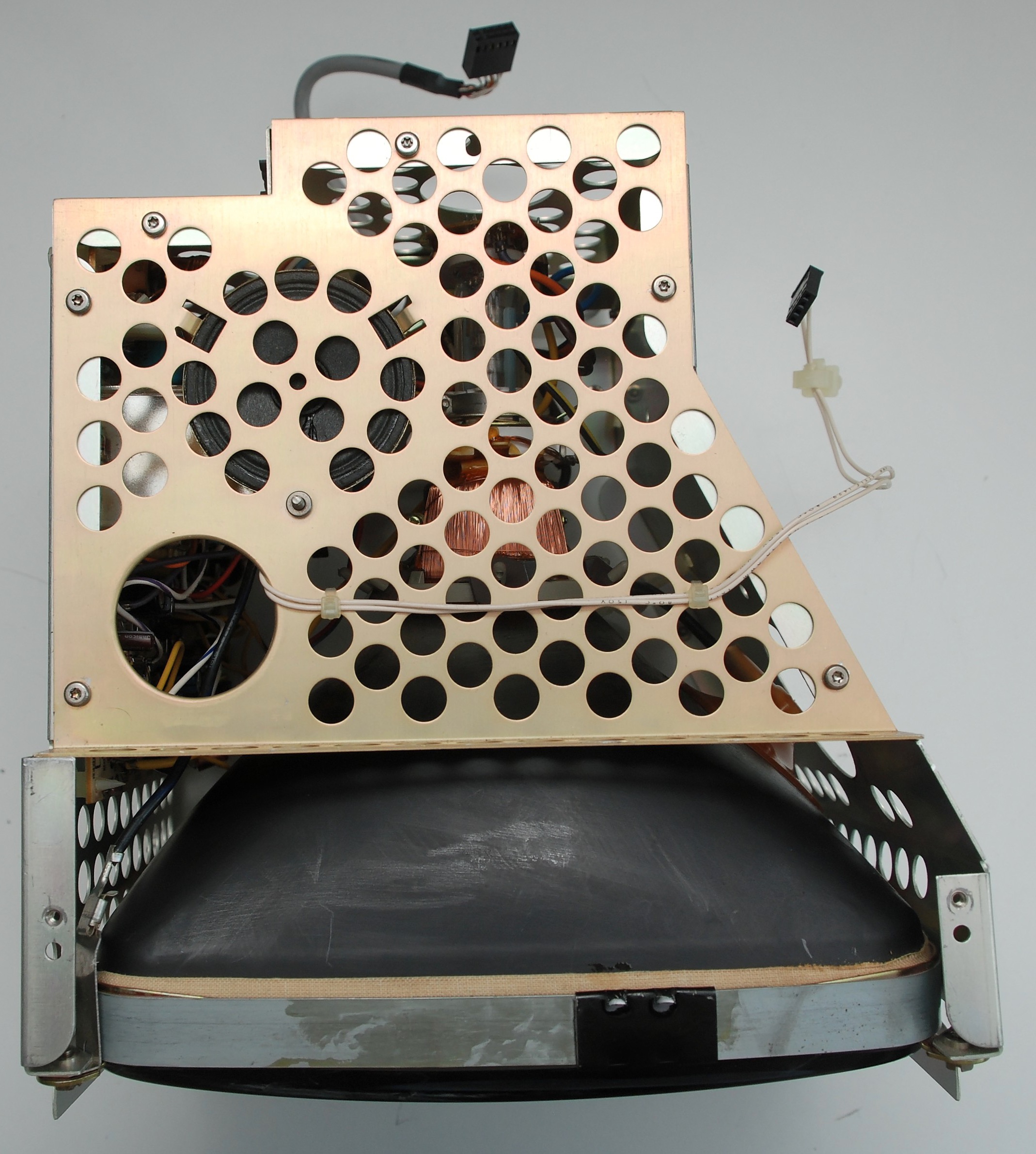
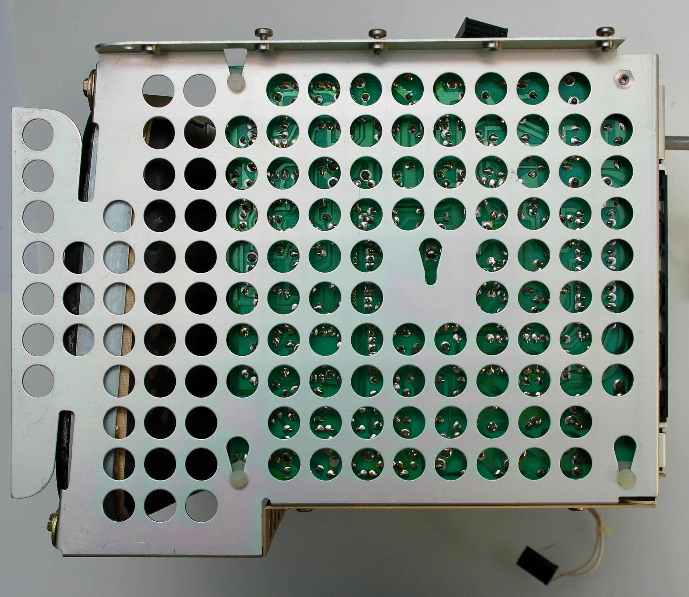
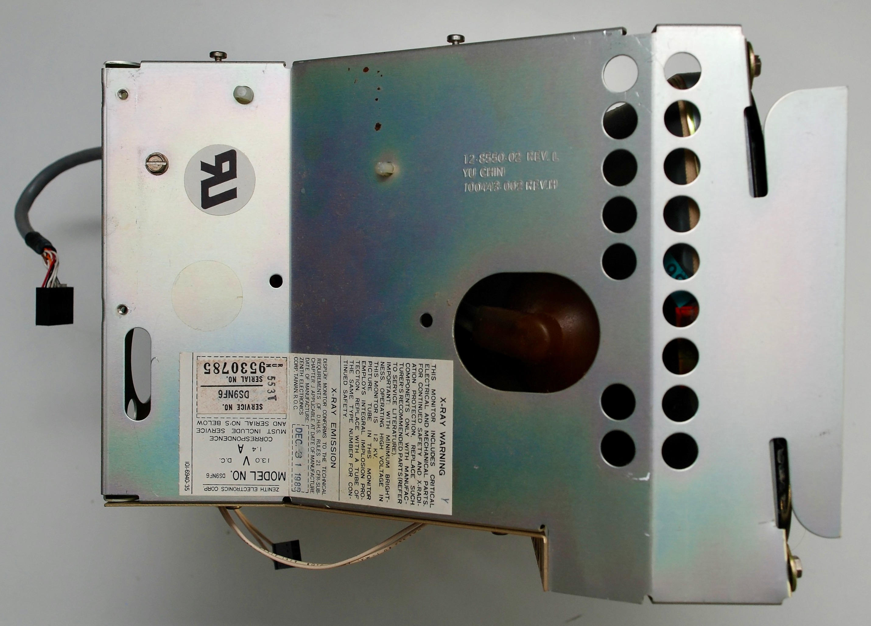
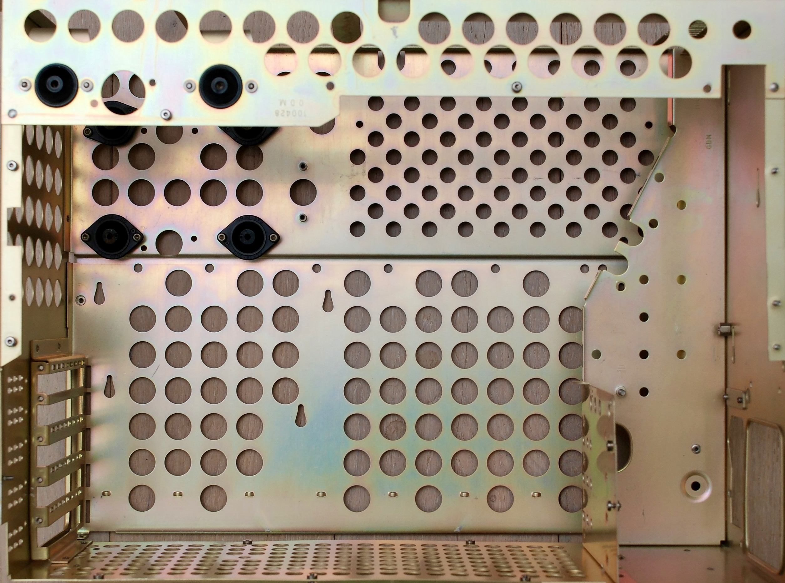
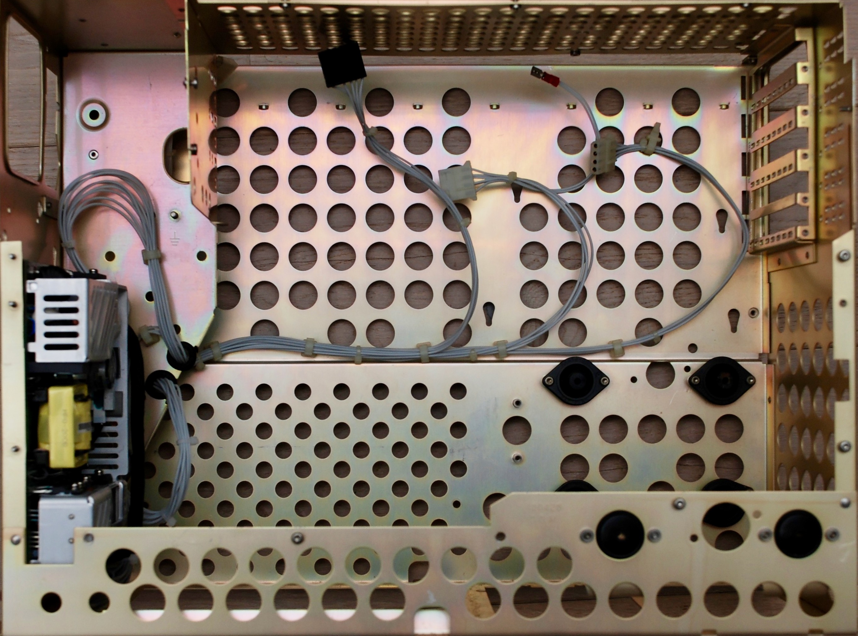
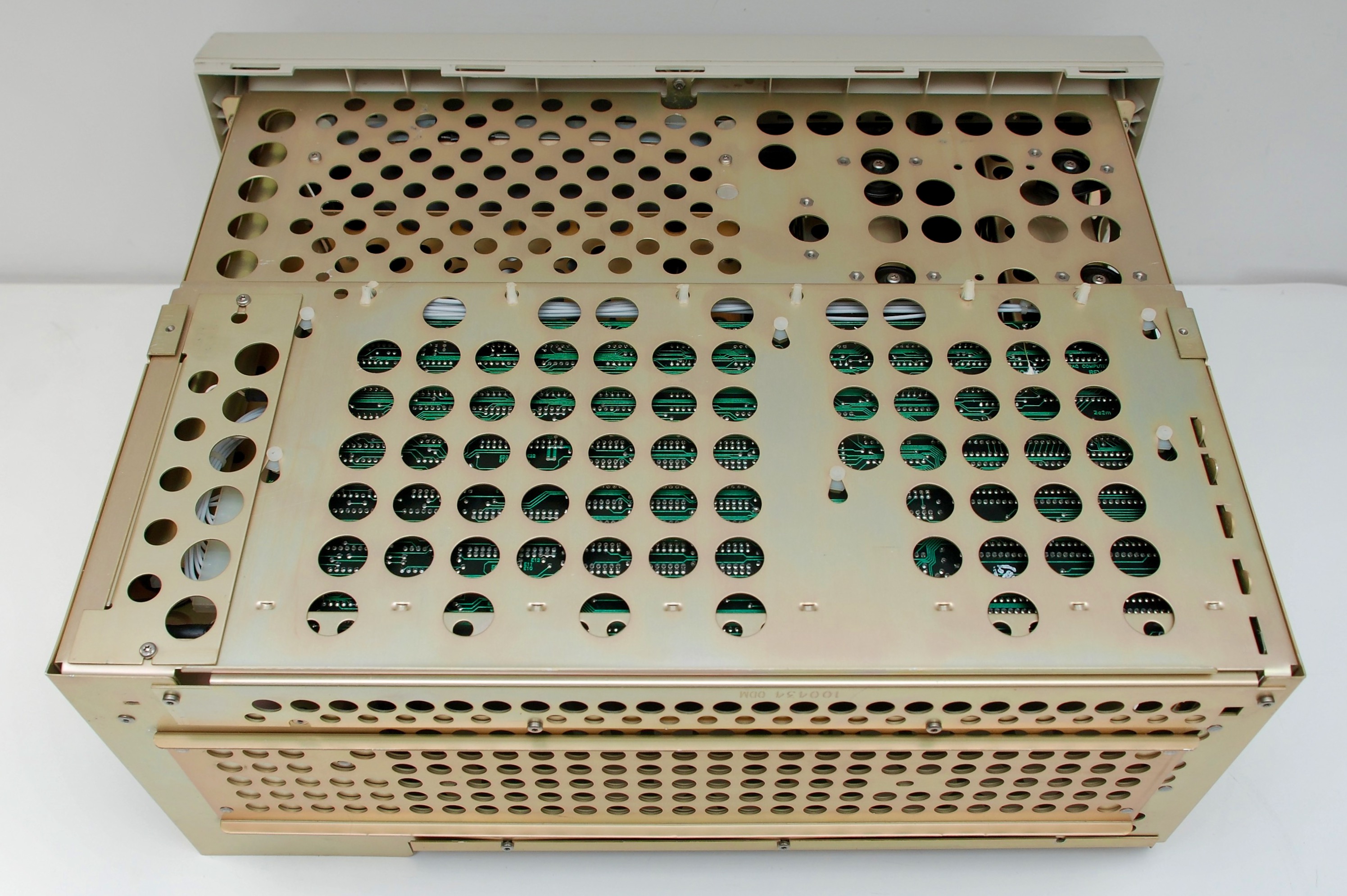
Chassis


Diagnosing boot issues
When booting, a set of diagnostics is executed and in case of failure, a status is reported on the screen. To read it use either the internal display, or connect an external monitor over 9-pin RGBI or monochrome composite cable. Don’t forget to set the appropriate display mode on the motherboard’s SW1 and check the two jumpers on the VDU (Video Display Unit) card.
The error code is 3 or 4 digit number, which first digits indicate the source of failure and last digits will be non-zero if the device tested bad.
| Error Code | Source of failure |
|---|---|
| 1** | System board |
| 20* | Memory |
| 30* | Keyboard |
| 4** | Printer / Disk Drive Adapter |
| 5** | VDU Adapter |
| 6** | Disk Drive |
| 11** | COM1 |
| 12** | COM2 |
| 17** | HDD |
In case of memory failure (code 201), the code will be preceded by the exact location of the erroneous chip. The location consists of 4 digits in the following format:
| Digit | Value | Meaning |
|---|---|---|
| 1st | 0-3 | bank number |
| 2nd | 0 | always zero |
| 3rd, 4th | 01 | row 0 |
| 02 | row 1 | |
| 04 | row 2 | |
| 08 | row 3 | |
| 10 | row 4 | |
| 20 | row 5 | |
| 40 | row 6 | |
| 80 | row 7 | |
| 00 | parity row |
For example error code 1008 201 means memory error, bank 1, row 3. If the row location does not match, all chips and memory chip select circuits (CAS, RAS) should be checked.
In case of severe errors, after displaying the error code, the booting will stop and CPU will go into halt (no activity on address/data lines). Otherwise the booting can continue. A correct boot will be signalled with a single beep. Continuous beep or repeated short beeps indicate power supply errors. One long and two short beeps will indicate failure of the VDU adapter.
Replacing Compaq Portable Power Supply
My original PSU came faulty. I tried to fix it but failed. There was something non-obvious wrong that cause the switching transistor to blow. I ran out of transistors diagnosing it and decided to replace the whole power supply with a modern unit.
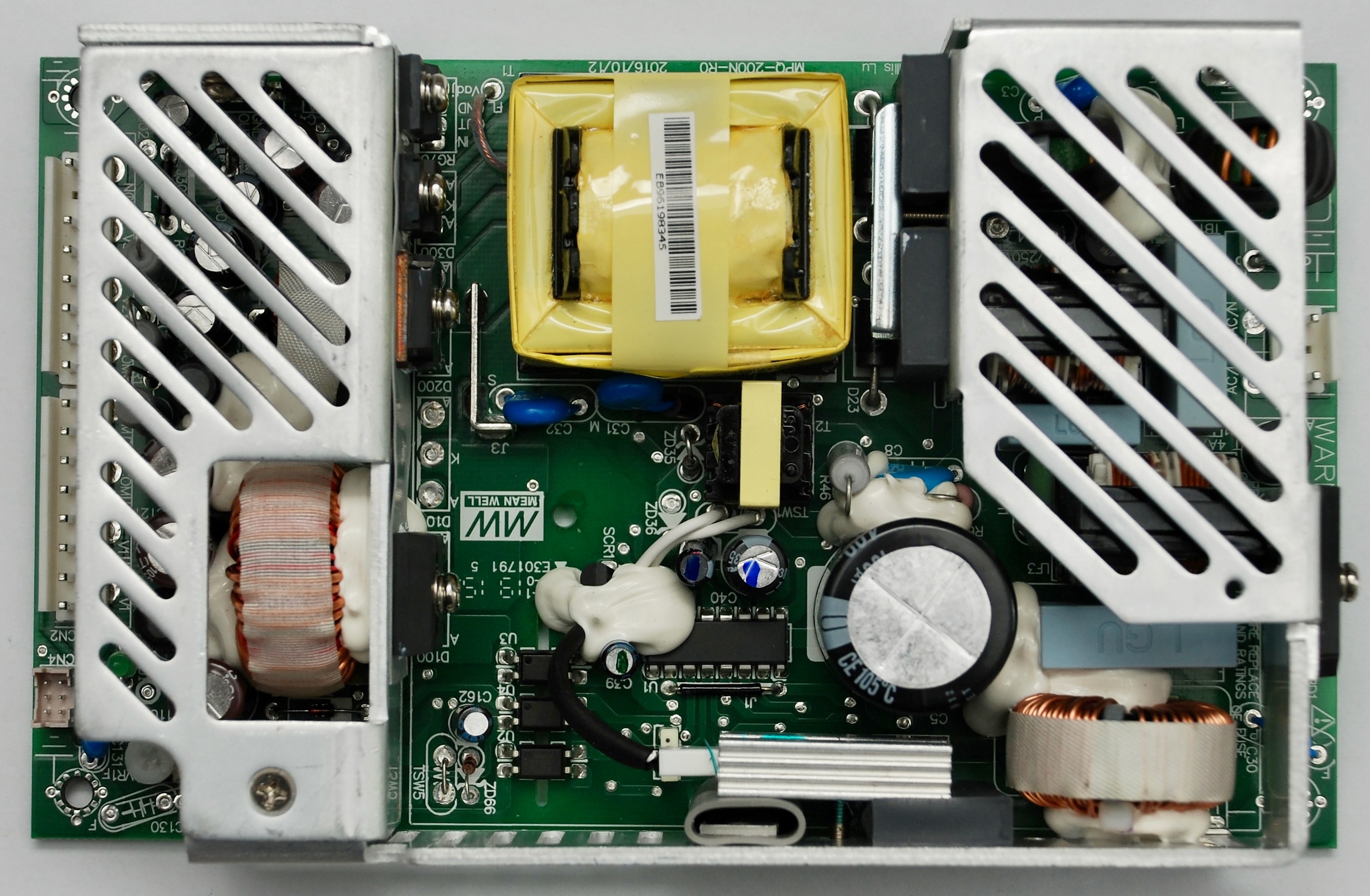
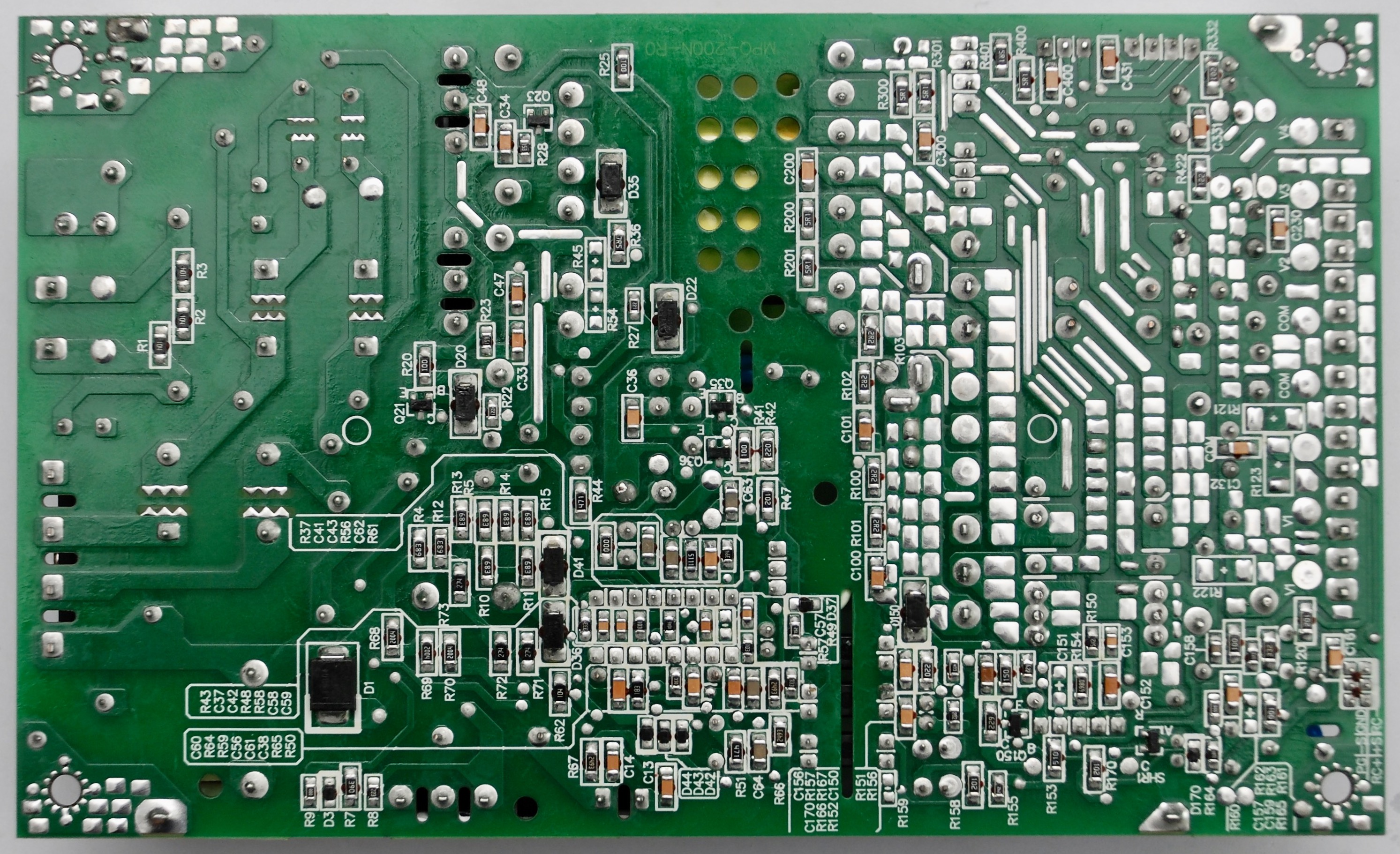
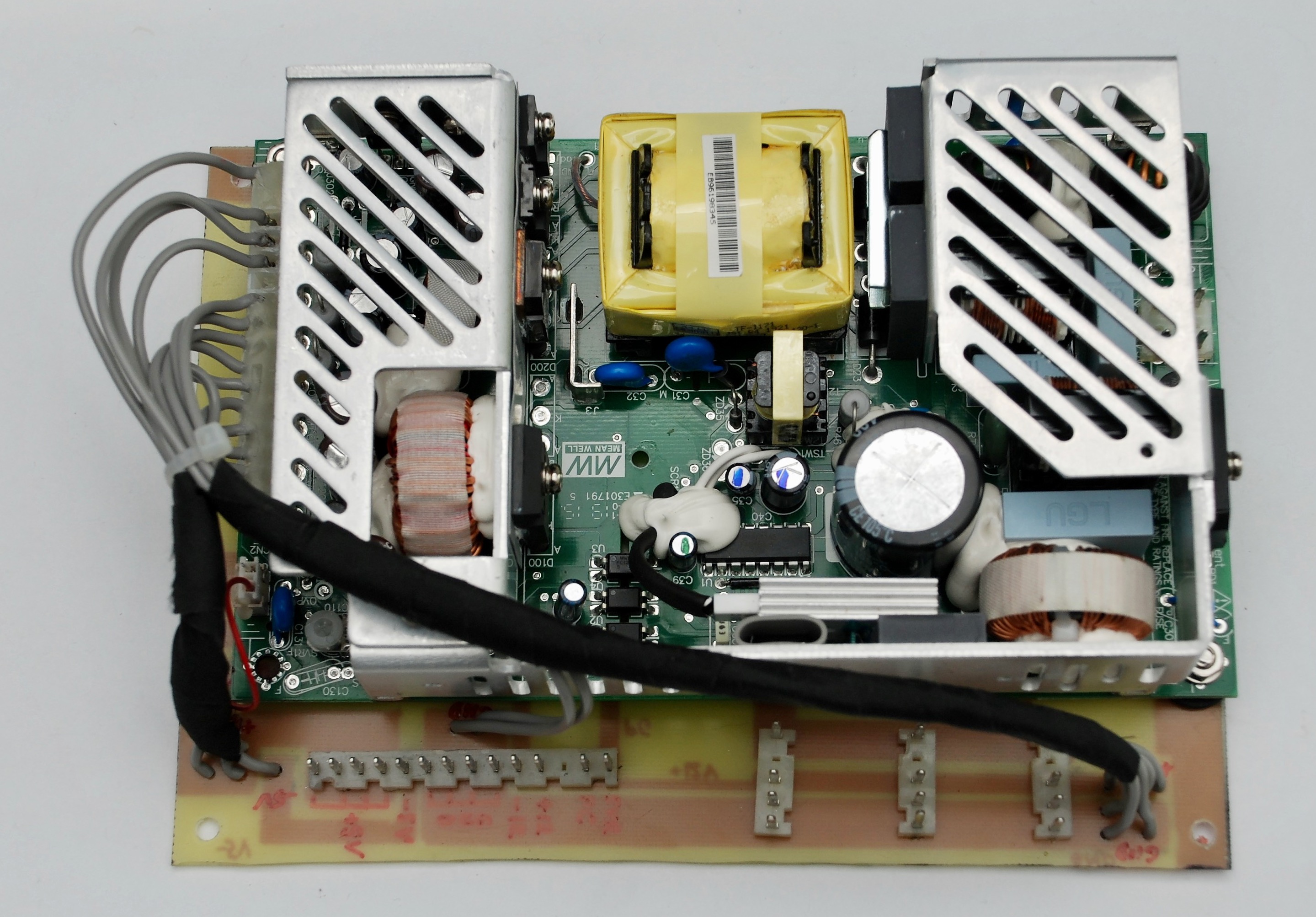
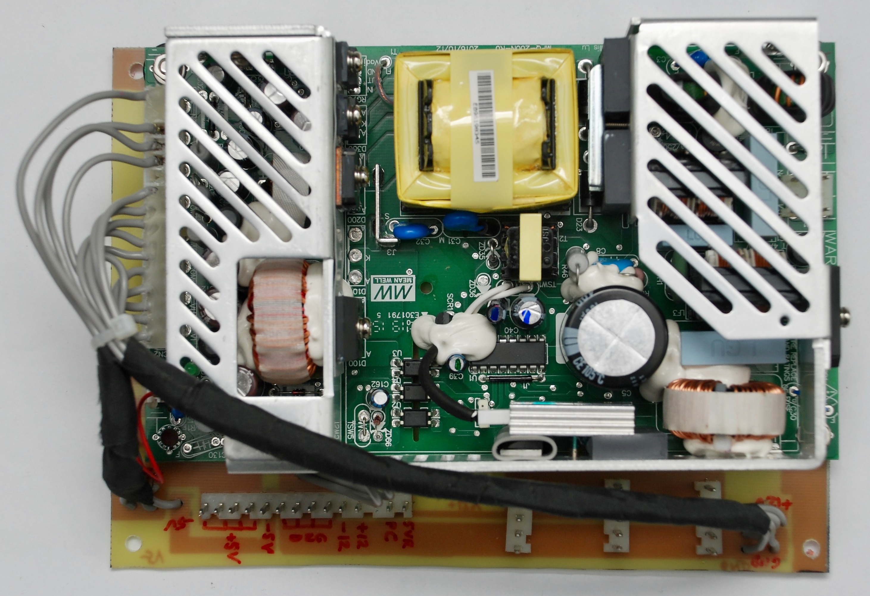
The replacement unit I found is Meanwell MPQ-200B. It has all the correct voltages at sufficient ratings: 5V, 12V, -5V, -12V. It has a power good signal. Finally, it is smaller than the original PSU, so it should fit the space.
The connectors have different pinout than Compaq PSU. Meanwell has two connectors: one (split into two parts) for providing the power and a smaller one for control signals. I did not want to destroy the original cable, so I decided to build an adapter. Because the board size of the new PSU is smaller, it is possible to build an adapter board of the original side, place the PSU on top of it and use the remaining space for transplanting the original connectors.
The input AC connector has compatible size, but different shape of the pins. It can be replaced directly on the new PSU board, so the AC cable can be plugged into the PSU. The ground cable connector is different, but the new plug can be easily clamped on the cable and also plugged to the PSU. The output DC connectors can be removed from the original PSU and placed on the adapter board.
The pinout of the Compaq PSU is marked on the PSU board. Meanwell PSU has pins marked too, but I learned the markings were incorrect. This could have fatal consequences. Please measure the voltages at each pin and use the empirical values when making connections.
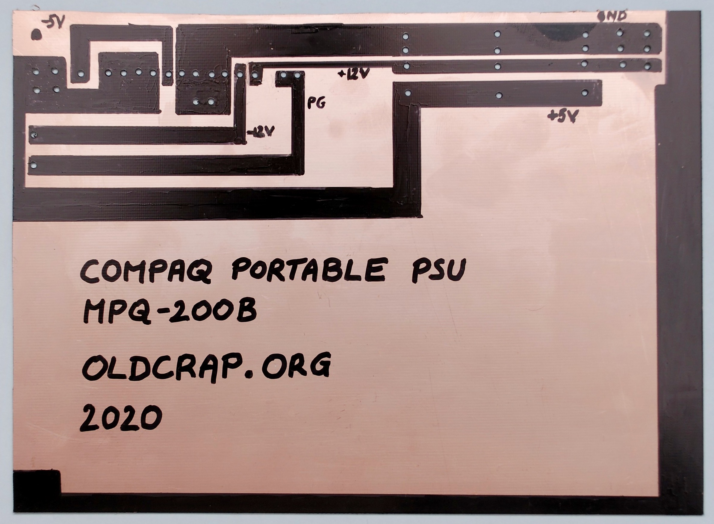
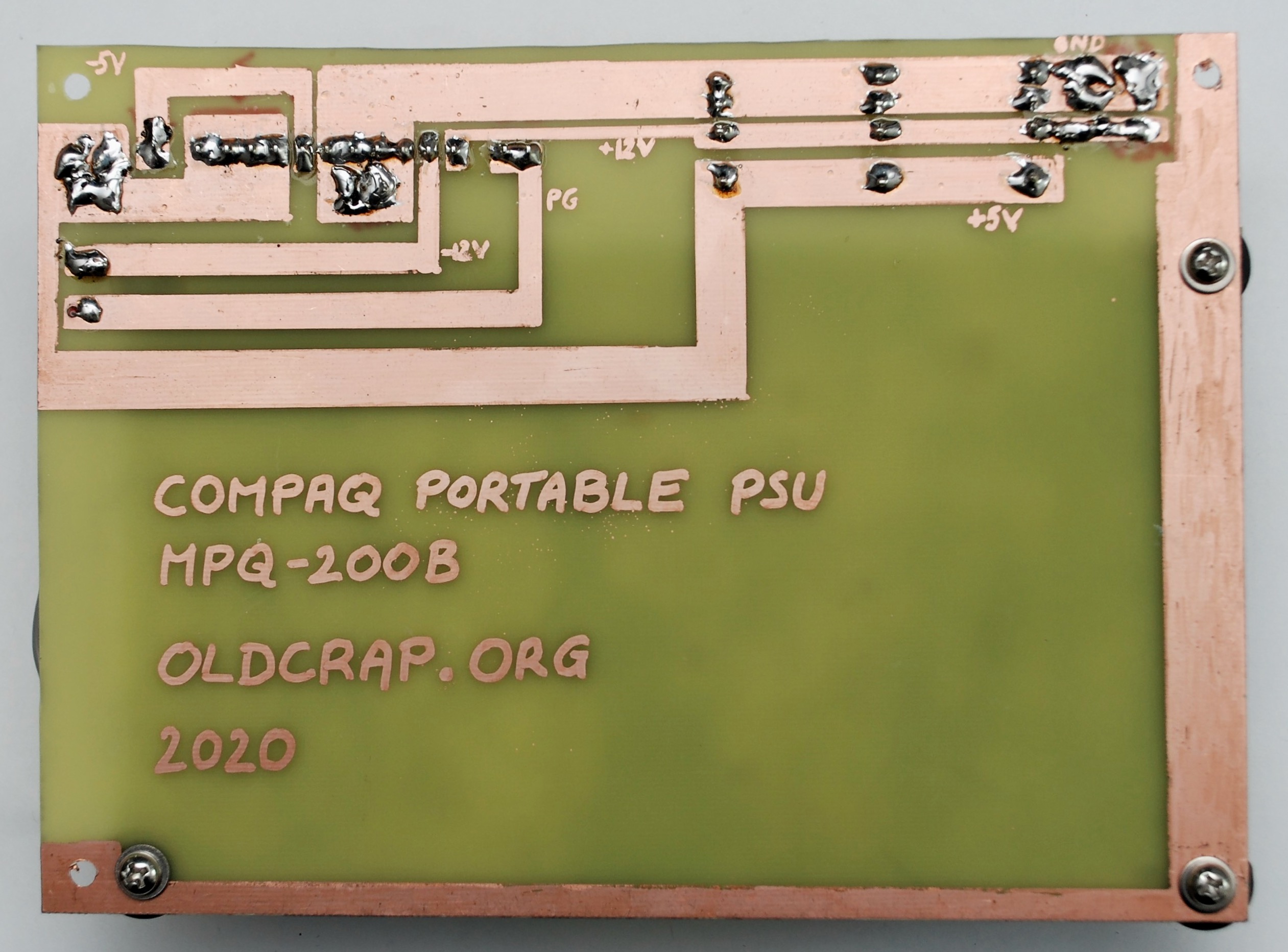
Here is a first version of the adapter board. It is not correct with handling the power good signals, but it demonstrates the idea. The voltages are linked one to one between the PSU and the old connector. For some of the signals (ground, +5V) multiple pins/cables are used and I retained this concept because of the current levels that will travel through these cables.
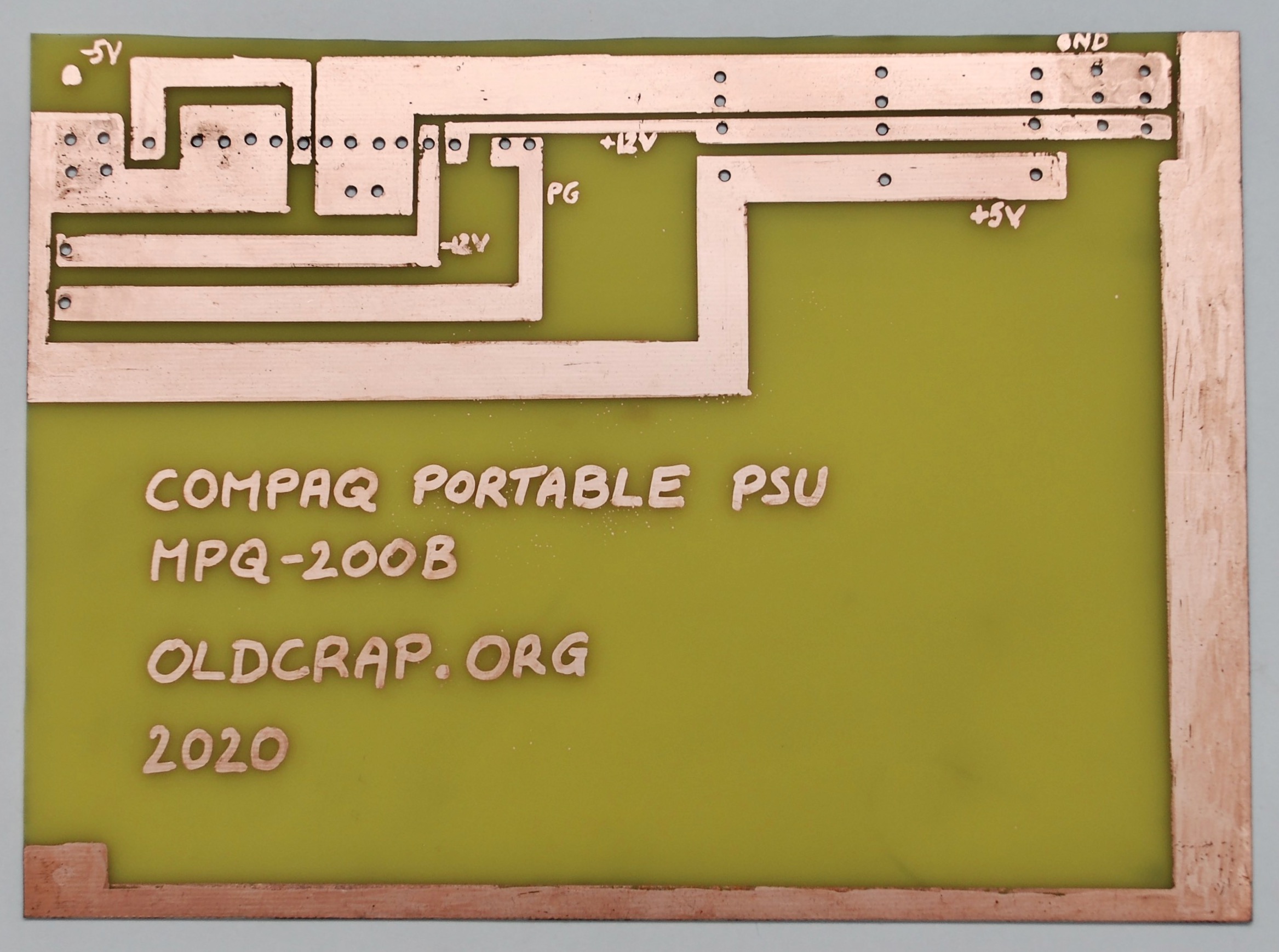
The old-school process of etching the board.

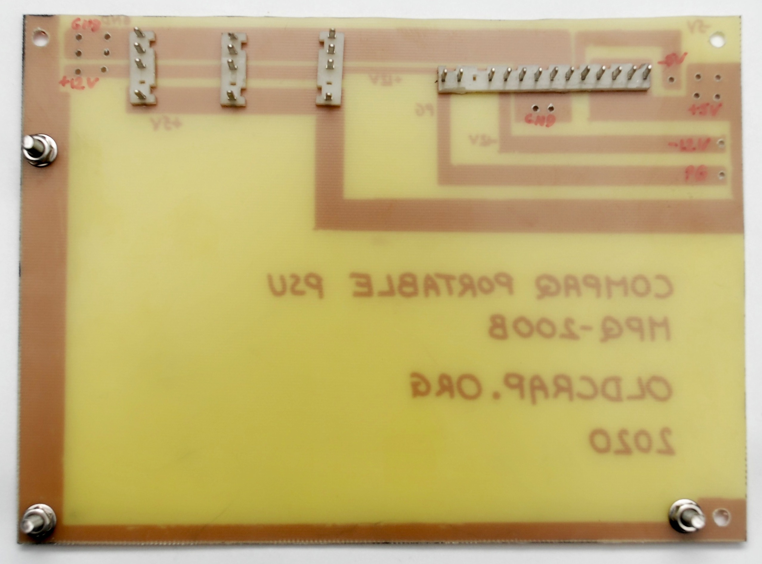
The cables connected to the PSU plug – please note the cable at pin 4 is incorrect and should be moved to pin 3 – this is because of wrong markings on the PSU. The connector on the right is used for power good signal and ground.

The adapter board with the PSU mounted and connected.
PSU has an output signal called Power Good – it goes active (+5V) when all the other voltages are ready to be used. Compaq Portable has two inputs used to indicate the power readiness by the PSU:
- +5VR (pin 1) – this is a +5V regulated power source used to drive the power good logic on the motherboard
- PC (pin 2) – called Power Good / Reset. It is used to drive the chips out of reset and to enable clock generation
Here are parts of the schematics that show how the signals are generated by the PSU and consumed by the motherboard:


When I initially tested the new PSU with the motherboard, I connected both PC and +5VR pins to the PSU power good signal directly. It seemed to work fine at first, but with ISA cards installed, there seemed to be load significant enough to drive the power good voltage down to 2V which caused the board to reset.
I separated the PC and +5VR signals and connected the +5VR to the +5V on the PSU. This improved the situation, but the problem returned with the CRT and FDDs connected.
I added a buffer between the PSU power good signal and PC input on the motherboard – a TTL chip (7409 AND gate) with open collector output, which input was connected to the PSU power good signal and the output driven by the +5V from the power supply. (It can be any other chip with open collector output that can just buffer the signal)
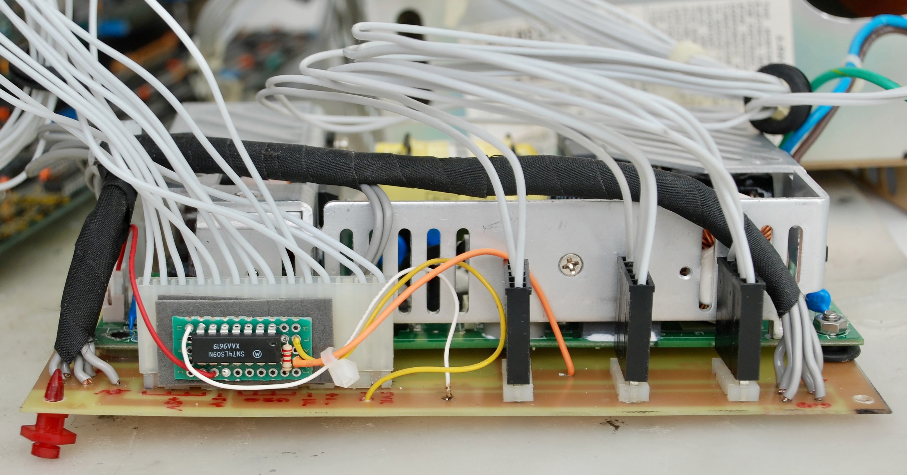

This caused the computer to be powered on correctly on all attempts. The PSU was ready to be mounted.

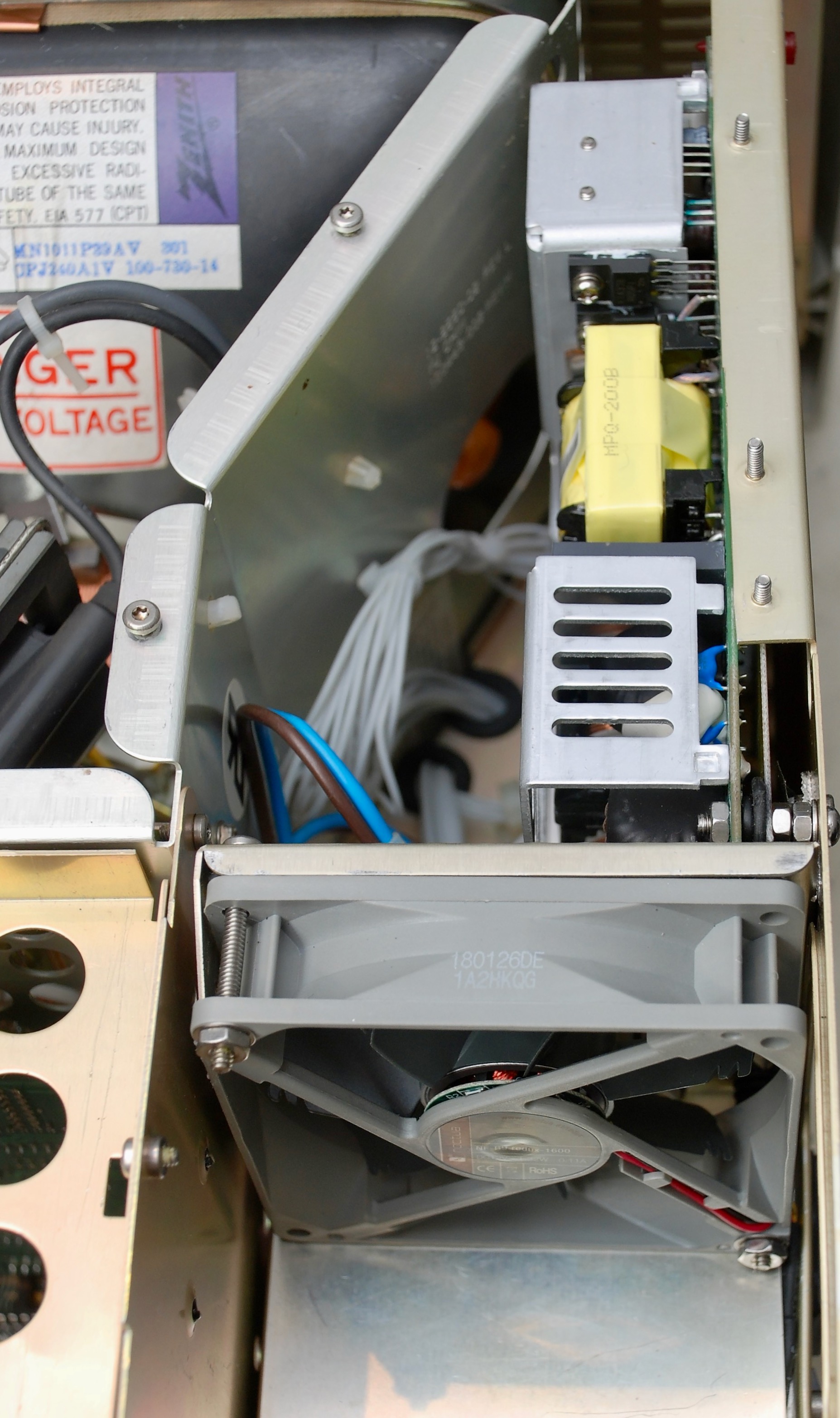
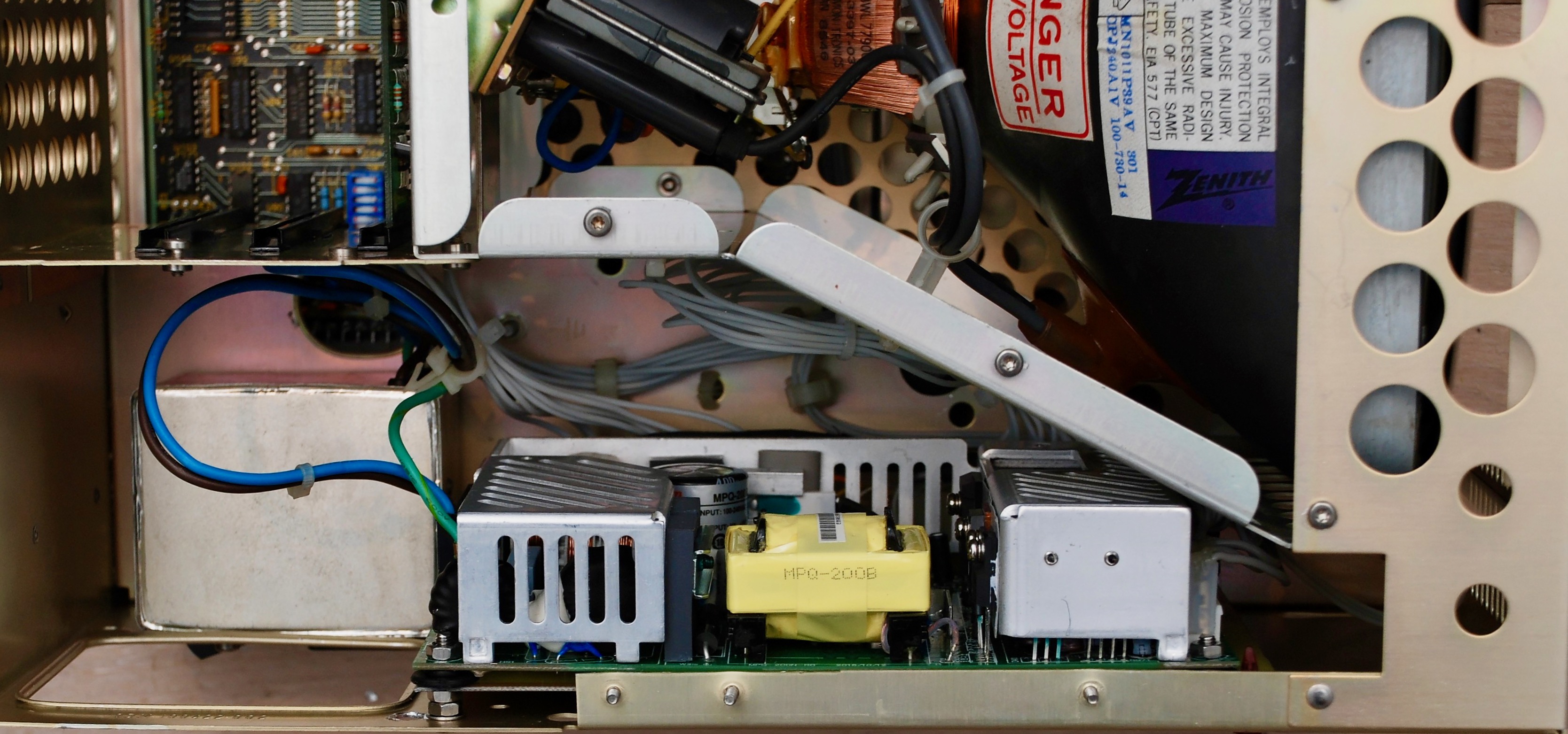
The new PSU does not fit the chassis in the exactly same place as the old one. The original PSU is thinner on one side close to the front and the new PSU is of even height and must be positioned closer to the rear of the chassis. But there is enough space to fit it – the new mounting holes must be drilled in the chassis.
With the new PSU, the old fan will not fit the original space and must be positioned on the other side of the mounting bracket. My fan was rated for +110V, so I replace it with a new +12V which I connected directly to the PSU.
“The motherboard and ISA cards contain tantalum capacitors, which are prone to failure and shorting the power lines to ground. It is a good idea to replace all polarised tantalum capacitors, for example with modern electrolytic capacitors” The vintage Macintosh community has been replacing electrolytic capacitors with tantalums because they are supposed to be longer lived and reliable. I have no idea how these things work, but there’s more than just one or two people recapping Macs who have done this. I’m going to do more research on this, you might want to also.
Yes you are right. Electrolytic capacitors when age leak and dry out causing the capacitance to go down and esr to go up. They stop accumulating charge. Those tantalum capacitors when aging break and short the terminals. I don’t know if this is for that particular series of the capacitors or all tantalum capacitors but this is an empirical fact.
I think aging capacitors are the least of Pawel’s concerns with this one, he’s virtually rebuilt it from scratch 🙂
Of course you’re right, arnold. Either way you’re buying a few more years with cheap parts and just a little soldering. For the win! Before the popularity of CompactFlash adapters in place of hard drives and further possibilities for virtual floppies on usb sticks (Gotek), I would not have the patience to spent a single minute with a Compaq Portable.
Looking far ahead, by the time the capacitors need replacement again, some amazing new technologies may be with us. I’ve already fantasized about adding an e-Ink screen, an idea originally conceived of for replacing the original Mac CRTs. Refresh rates are slow, but these dinosaurs are also slow, and unsuitable for modern computational tasks. Plus they were monochrome anyways! Giving weather reports or similar such things on the screen of an eye-pleasing antique computer seems like a suitable fate! But, I’m probably not going to get further than making comments from the peanut gallery.
would you build one to sell ? I love old tech but dont think im apt enought to build what you did.. but i need one bad…
No time unfortunately. I can hardly find enough time to document new machines. But it is not so hard! You can do it.
I realize that you wrote this article several years ago, but do you remember where you got the information on how much current at each voltage is required of the power supply? I’m trying to figure out if I can use a picoatx psu along with a little adapter board somebody is selling on ebay.
I have seen a photo of the adapter that you mentioned. I have never seen one in real life. It is used with a pico Power supply to replace the original one. The brick for the pico fits into the same hole as well.
I want one too.
I think I don’t have the current draw numbers. I estimated them based on what is common (for example what portable 2 specifies) and as far as I remember got a PSU that has some buffer. But my memory is foggy.
In progress to restore my Portable. But doing that here in Brazil is a nightmare. No parts available.a all.
Fixed PSU, Motherboard, CGA, Floppy card (tantalum issues)
Not possible to recover sixpak (bought a new one just to keep identical)
Missing flyback (waiting for a new one to arrive) .. not even sure if other areas from monitor are ok.
Did the foam/foil replace and still a dead 301 keyboard (adapted another XT keyboard with a voltage regulator to 5 and everything is ok at mobo side)
Look like each shipment was sent with a different keyboard pcb .. hard to trace it.
Mine looks like same as yours . but has an extra ttl and an eprom .. also using a different processor.
Do you have a dump from that microcontroler in keyboard?