


Resources
Documents
Internals
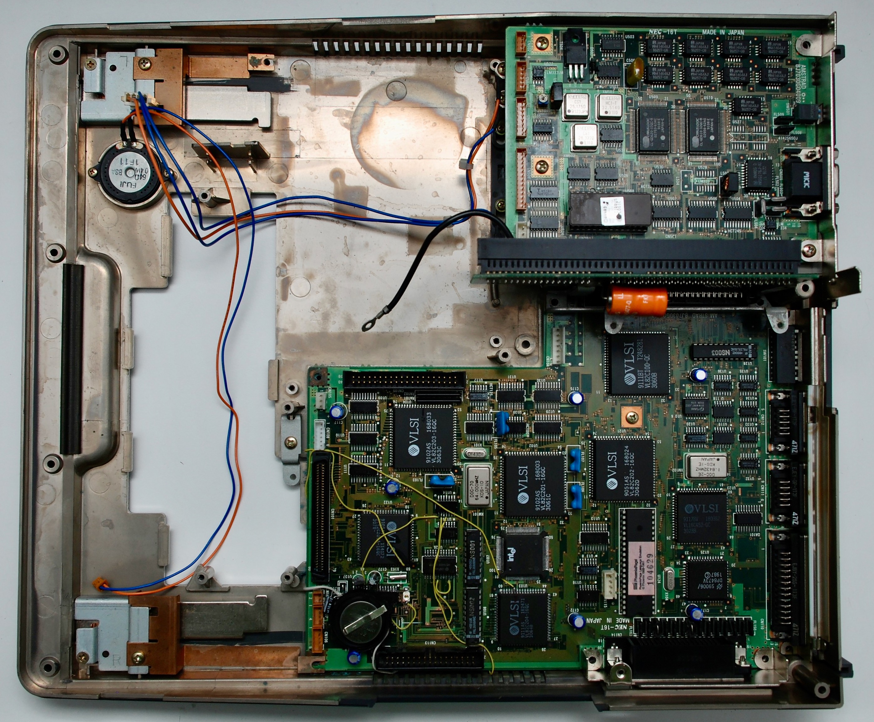
Motherboard
Somehow I forgot to make pictures of the motherboard. So this is only front of a dirty board after dismantling the machine. Now the computer is all assembled.
BIOS entry key is F2 during boot or CTRL-ALT-S from DOS prompt.

Power Supply
Rubycon RPS-07


ROM/RAM Module


Graphics Card


ISA Interposer Board


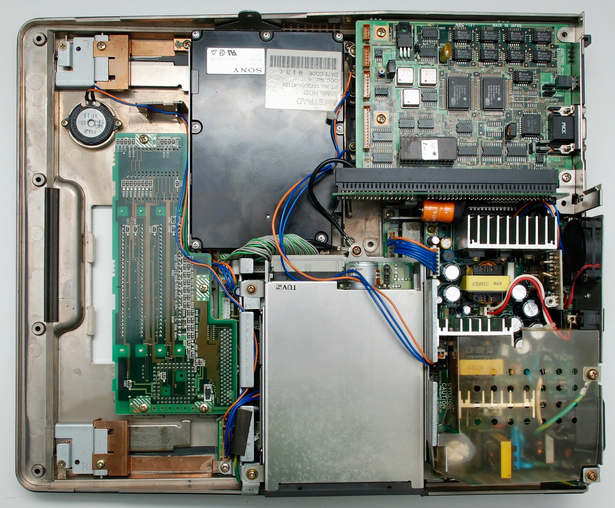
Hard Disk Drive
80 MB Sony SRD3080C-50. HDD Type in BIOS is 24.


Floppy Disk Drive


Display/Keyboard Adapter Board


LED Panels


Display & Backlight Inverter Board


Display
Epson EG9005-F-LS-2


Keyboard


Battery


Reassembly


Fixing ALT-386SX
Phoenix BIOS Beep Codes
When BIOS boots, it reports errors of the power-on self tests in a form of audio beeps on the built-in speaker. The meaning of the error code can be found on the BIOS Central web page.
Checking the Configuration Switches
There are two sets of switches at the back of the computer. For first boot it is probably best to set the smallest memory size and internal display. When there is less memory available than configured, BIOS will report a beep error code. OFF = switch is UP, ON = switch is DOWN.
| SW1 | SW2 | SW3 | Memory Size |
|---|---|---|---|
| OFF | ON | ON | 512KB |
| ON | OFF | ON | 1MB |
| OFF | ON | OFF | 2MB |
| ON | OFF | OFF | 4MB |
| Switch | Meaning | ON | OFF |
|---|---|---|---|
| SW4 | Page mode | Always ON | – |
| SW5 | Wait states | – | Always OFF |
| SW6 | Clock | 8 Mhz | 16 Mhz |
| SW7 | Display | Color | B&W |
| SW8 | Serial | Enabled | Disabled |
| SW9 | Pipeline | Always ON | – |
| SW10 | Drive B: Type | – | Always OFF |
Recapping Power Supply
All electrolytic capacitors used in the Rubycon power supply are of poor quality and they all leaked. The effect was that the output voltages were much lower than required. Replacing the capacitors restored the correct voltage levels.


Checking SIMM Connectivity
When there are memory problem reported by the BIOS, it makes sense to check the SIMM connectivity to the chipset, especially when there was a battery leak that could have damaged the PCB traces.
SIMM modules are organised in Columns (0, 1 – also called banks) and Rows (1, 2).

Stored data bits are divided between rows: bits 0-7 are stored in row 1 and bits 8-15 in row 2. Therefore two SIMMs must always be inserted into row 1 and 2. Column 0 is used as a lower memory location and must be always populated with SIMMs, as it is used to boot the machine. Column 1 is optional and may be used for a memory extension.
SIMMs are wired to four chips on the motherboard, VL82C202 (Memory Controller), VL82C203 (Address Buffer), VL82C204 (Data Buffer), VL82C205 (Page Mode / Interleave Controller). Some of the signals are connected through a resistor soldered to the bottom side of the ROM/RAM board. If a resistor is present, when checking the connectivity of the traces, please locate and use the connection after the resistor, not at the SIMM.
| Signal | From SIMM Pins | From SIMM Column | From SIMM Row | Through Resistor | To Chip | To Chip Pins |
|---|---|---|---|---|---|---|
| Data Bits 8-15 | D0-D7 | * | 1 | – | VL82C204 | D8-D15 |
| Data Bits 0-7 | D0-D7 | * | 2 | – | VL82C204 | D0-D7 |
| Column Address Strobe | /CAS | 0 | 1 | R337 | VL82C205 | CAS0L |
| Column Address Strobe | /CAS | 0 | 2 | R338 | VL82C205 | CAS0H |
| Column Address Strobe | /CAS | 1 | 1 | R339 | VL82C205 | CAS1L |
| Column Address Strobe | /CAS | 1 | 2 | R340 | VL82C205 | CAS1H |
| Address Bits 0-7 | A0-A7 | * | * | R321-R328 | VL82C203 | MA0-MA7 |
| Address Bits 8-9 | A8-A9 | * | * | R329-R330 | VL82C202 | MA8-MA9 |
| Address Bits 10-11 | A10-A11 | * | * | – | n/c | – |
| Write Enable | /WE | 0 | * | R331 | VL82C205 | RAMWA |
| Write Enable | /WE | 1 | * | R332 | VL82C205 | RAMWB |
| Data Parity Out | QP | * | 1 | – | VL82C204 | MDPOUT0 |
| Data Parity Out | QP | * | 2 | – | VL82C204 | MDPOUT1 |
Pinouts of the chips used in the table above:


Fixing a Battery Leak Damage
Leaking CMOS battery can cause severe damage to the board. It can oxidate and dissolve traces and vias.

The board can be cleaned with vinegar. Vinegar should not be left on the board for too long and can be removed with clean water (possibly with some baking soda added).

In order to fix the traces, the most damaged chips should be removed from the board to reveal more damage to the traces beneath the chips.

Now it is best to use some super fine grade sanding paper to remove the varnish and reveal all the traces.

Making photos of the board and using a paint application to draw multiple colors on top of the traces will tremendously help in checking the connectivity and fixing broken traces.


Traces can be fixed with a special ultra-thin wire. It is possible to solder the wire directly into the vias on the board. The mesh looks messy, but does the job. Before soldering the SMD chips back to the board, use PCB coating varnish to protect the uncovered traces. When all soldering is done, use more coating on all the uncovered traces and soldering points.


WOW! What a great amount of effort and kindness to share this. It’s helped me alot find many faults
on the 386 board that I have been working on. Much credit you deserve for this. THANK YOU!
Thank you
I re-capped the PSU and got my ALT386 powered up but then the display went blank the following day.
Still boots as I can hear the boot process and the floppy booting. Checked the orange power wires on the
VGA board for CN502,CN503,CN504,CN506 and none of them have any voltage, most of the blue wires have no voltage either. No display from the VGA monitor port either. Thinking the VGA board may have a fault but can’t do much checking without the schematics.
It can be just the connector of the vga card. Or maybe you changed the position of the two display switches?
Good afternoon Pawel, good to hear from you and thanks for the reply. The machine was working great after the caps were replaced along with the cmos battery and good clean of the board. No dip switches were changed, I have the manual BTW. Screen just started to flicker then went blank. Powering off I see the screen light up for a brief second. I think the display draws all it’s voltages through the ISA riser and into the VGA card. The main power board has all the correct voltages (5V 5V 12V -12V -19V GND GND). I may have to strip her down again (excuse the pun) 🙂 and have a poke around with my multimeter. I did notice that the large D1833 NPN power transistor on the VGA card was cold, but did have 12V on the collector was but not drawing any power. Your very clear photos have helped very much, thanks for those again.
Good luck! I hated putting that cover back together, it was so tight inside. Would you be willing to share the scans of the manual? It seems to be absent in the Internet today. Thanks.
Yes, she was tight inside (no pun intended) with all those cables. The manual is too many pages to scan and would take me forever and a day with the scanner that I have. If I can find it online, then I will post a link.
Very helpful, I believe I have now diagnosed mine with trace damage from a battery that didn’t seem to be leaking, and possibly a cap too. I very much appreciated your comments on FB and the link to here.
Thank god for microscopes and people who have gone before!!
Hopefully I’ll break out the bodge wires and get it running soon 🙂
Great, I am happy you can fix your machine. Thanks for the good words!
>>One thing of note is that the capacitor is part of the speaker circuit, so if the speaker volume is low, you know that the capacitor should be removed immediately
Thats exactly what I did today.
I turned my one on after Years again and could barely hear the speaker. Was expecting the worst at the Battery but it seemed to be ok. On the second view I found the leakage at the SMD Cap. Had no matching one so i replaced it with a Standard 25μ and it works.
Finally have a map of my bad connections, seems that the 33uF SMT cap (C121) near the memory connector had also gone, distributing corrosive goo under U144, so not a dissimilar state to yours. I have a large scale image printed, and hope to get on with the repairs from tomorrow. Bodge wires are definitely going to be required!!
I finished the rats nest of bodge wires, luckily my corrosion wasn’t as bad as yours, and it now runs again!!
Thanks so much for all the time and effort working through this yourself, it’s certainly made things much easier for me and without it I don’t think I’d have mine running again. It has tested my patience and soldering skills though!!
Good job I am happy you saved your machine! I find this work an awkward way of relaxation and mastering patience. My wife does the same in the garden.
Well, I had a brief diversion with my Alt-386, in that I lost 12v from the PSU. After a lot of troubleshooting,it turned out to be the short 1 inch cable from the PSU to the mainboard!! Some of the connectors in the 7 wire plug had failed, giving an intermittent 12v connection. It’s all repaired now, reassembled and fully running again 🙂 Once again, I appreciate your excellent site, without which I’d have probably given up! I has tested my patience and I really do know what you mean about it being a strange and awkward way to relax! I also relocated the battery, and the capacitor that killed it has been replaced with a tantalum, so no more leaking!! One thing of note is that the capacitor is part of the speaker circuit, so if the speaker volume is low, you know that the capacitor should be removed immediately 🙂
Excellent job you did with your machine, congratulations!
Does anyone know what the free “CN304” next to the 387-Soket is used for? Looks interesting.
Hi, very good article. I saw, you replaced the original rechargeble battery with a button cell. Isn’t it necessary to disable the charging circuit for it, to prevent damage of the battery? If so, how did you do this?
That is a good catch, I probably did this wrong and did not notice the original battery was rechargeable. This may be dangerous to charge that type of battery. I will remove it. Thanks!
If you have a solution for disabling the charging circuit, let me know how to do it. Thanks a lot. 😉
You would require a 1N4148 diode in series (reverse biased) with the battery positive terminal. It is much more easier to just purchase one of those 3.7V rechargable battery packs used in cameras and mp3 players.
Thank you for your reply. Yes, that’s what I’ve been thinking about as well. The best solution whould be to buy such a rechargable battery.
Does it matter if the battery is Nicd or Nimh?
Another question: Unfortunately, the capacitor (??) C121 has come loose from the board. Since I can’t find a schematic or something on the internet: Can someone tell me what exactly this part is and what it’s used for? Unfortunately, I am not an electronics engineer and do not even know if this is actually a capacitor. But I found the part here on one of the pictures. It is labeled “4W 33 10V”. Obviously the circuit board has also taken some damage because it is blackened in the area directly under the capacitor.
Does anyone know the problem and can help me out?
Translated with http://www.DeepL.com/Translator (free version)
@jwich71
If you have experience in soldering you should be able to replace the capacitor. If you see signs of corrosion you can remove it with some drips of vinegar as in the pictures above. For cleaning up I use 96% alcohol.
The C in C121 means it is a capacitor and the value would be 33uF 10V. Make sure it is the same type.
Just acquired one of these. All seems good but BIOS comes up with F2 during boot but then hangs – you cannot do anything and no time date shown or cursor. Also, when booted to DOS prompt, CTRL+ALT+S does nothing. Also, should the reset button do something – it does not seem to! Any help would be greatly received. Thanks in advance.
Could be a power issue on obe of the voltage rails, have you checked re-capped it and checked all the voltages ?
Maybe also try re-seating the RAM modules and checking all cables are correctly fitted.
I just started Commander Keen on my device on an external VGA TFT and the colors looked very reddish odd. I remember playing it 25 years ago surely on an external CRT and cant remember any of this.
Now I’m not sure if my machine has a fault or if this is an artefact of the VGA output in combination with an modern TFT and the graphic mode used in Commander Keen. I tried different old Games and Windows 95 and could not reproduce similar reddish colors.
First, many thanks for all your help: In the meantime, I successfully replaced the faulty C121 capacitor with a 33 µF and also replaced the battery with a new NiMH 300 mAh.
The Laptop now powers up with POST but I then get this error: Invalid configuration information – please run setup program. Hard disk controller failure. I can hear the hard disk spinning up, but after setting the Type to 80 MB in the BIOS, fdisk cannot find my disk. The hard disk model is a Sony SRD3080C-50 AMSTRAD 80Mb HDD Date Code: 9211.
Does anyone have any idea what the problem could be?
Did you set the hdd type to 27?
I tested with type 24 (80MB) and type 35 (76MB). And just now I also tried type 27 (40MB). Unfortunately without success. After a long delay, the laptop finally boots from floppy disk. Fdisk then also needs a few seconds to start and then shows the message: “Error reading from disk”.
The parameters for that disk drive model should be: C963 H10 S17
Sounds more like a drive failure to me if it is correctly configured in the BIOS. The delay at boot means the hard drive is
it not responding.
I just checked my old original Harddrive. It’s the exact same 80MB SONY Model as in the Picture above. I wrote on it Cylinders 822 LZ822 Heads 4 and Sectors 51. As far as I remember, theese Numbers were detected by an 486 BIOS Hard Drive autodetection. I don’t know if a modern BIOS would show you theese Numbers.
Fortunately I found another old IDE disk that has the small 3 pin power connector. It’s a Quantum Fireball with 1GB capacity. I installed the disk today and lo and behold, the laptop now boots up faster again. I also noticed that the hard disk LED with the Sony disk was constantly on. Therefore I assume that the Sony hard disk is really defective.
The parameters printed on the Quantum are: C/H/S 2112/16/63. However, when I enter these parameters in the setup, the disk size is displayed with “***”. Maybe the disk is to big? Therefore I halved Cylinder to 1056, so the disksize is displayed as 506 MB. With these parameters I could format the harddisk under MSDOS 5.0 successfully with a capacity of 500 MB … I think this is more than enough, compared to the 80 MB of the Sony hard disk 😉
Thanks again for helping me!
To complete my post: The Laptop sill boots up with “Invalid configuration information – please run setup program”. But when I press F1 the Laptop then starts successful from hard disk. Is there still anything wrong?
I have to correct me: After repartitioning the disk I realized, that the full size was only 10 MB. So I experimented with the CHS parameter a bit. Now I use CHS 2015/16/63 (size: 991). Fdisk shows the disk as 506 MB. Hope I found the right config now.
Hi Guys,
I also have an ALT386-SX and am recapping the power supply at the moment. some of the caps were def bad.
initially it powered on (hard disk spun up) but like some others here no boot, no beeps.
so I’ll get the PSU fixed first and then do some more troubleshooting,.
fantastic webpage Pawel. great resource for the ALT.
did you ever come across the service manual ?
it would be really handy to have it.
Thanks
Ian.
Thanks Ian, I am happy that you liked my page. The service manual has not surfaced yet. Agree it would be very helpful to have it.
Hi Pawel,
one more question. did you match the caps exact spec for exact spec ?
any recommendations on the caps to use ?
were they from an assorted set ? or you ordered specific ?
thanks
Ian,
I don’t remember, but I usually match the capacitance and voltage equal or above. I did not order them for this machine, I have a cabinet with supply of various ratings to be used for recapping. I try to buy better brands, mainly Nichicon. For the stabilization of voltages in the PSU the capacitance can vary, if you have no exact match, try something close.
ok, perfect. I just ordered some nichicon and Panasonic from a local electronics shop. all exact matches so that was good.
thank you for the quick reply.
Ian.
Pawel, are there any specific pages from the manual that you would like to have. I would scan the full manual but I honestly don’t have a clue about doing that as I only have a basic scanner which is slow as crap.
Hi Arnold, not any specific page, I thought of making the whole document available to the public, because it is completely missing in the Internet today.
Ok, I see what I can do. Maybe I can get a library to scan it for me, other than that I will just have to take photos of every page.
Hi,
Thanks for all the all the Amstrad info you are providing.
I’m restoring my Amstrad Alt-286 but have a problem with the power supply (RPS-07).
I recapped it but I don’t get any +12V on the output connector. The other voltages are all present (+5V, -12V and -24V).
The measurement are done while the power supply is removed from the laptop and sitting on my work bench so the rest of the hardware is not stressing the power supply.
I’ve not been able to find any schematic/service info of this power supply.
Do you have any info for this power supply?
Or any suggestions how to find the problem preventing the +12 to work?
Thanks,
Mario
Hi I have acquired an Amstrad Alt-3865x and I would really like to use it but have no system discs. Any idea if I can still get these and where from. Thanks
Any MS-DOS disks should work, search for them on the Internet. The display switching tools are in the documents section of this post.
Here is the service manual and schematics
https://ia904502.us.archive.org/8/items/manual_ALT286_SM_AMSTRAD_EN/ALT286_SM_AMSTRAD_EN.pdf
Finally! Wonderful, thank you so much.
Good morning, first of all, thank you very much for this study, research article. A beautiful ALT386SX has come into my hands and its photographs and explanations will be very useful to me. A simple question, is the list of capacitors the original? I think they have tried to fix my source and added capacitors of different capacities. Thank you very much and sorry for the translation, I am Spanish.
Hola Javier. The list of capacitors is what I removed from my board. No idea what the values on the schematics are. The service manual is available and maybe it has this information, you need to check. I did not have the service manual when I was fixing my machine. Good luck and thank you for coming here!