Resources
Documents
Internals


Bootselector – step by step guide
Amiga 600 is equipped with Kickstart 2.0, which allows selecting boot drive from the boot menu. This is particularly useful when connecting an external drive like the Gotek USB floppy emulator. Even though, most of full disk programs will refuse to work as they have hardcoded access to the internal drive (DF0).
It is possible to install a hardware switch that will exchange internal (DF0) and external (DF1) drives by exchanging the drive select signals going from the drive controller 8520 VIA chip to the drives. It is not so easy as in Amiga 500, where the chip is replaceable and sitting in a socket, still possible.
We will mount a switch that will exchange signals _SEL0 and _SEL1 going to the 8520, right before the 8520 chip. The schematics required to understand the logic:


All pin positions described in the below text are related to the board being viewed from the top with ports up (normal operational position of the computer).
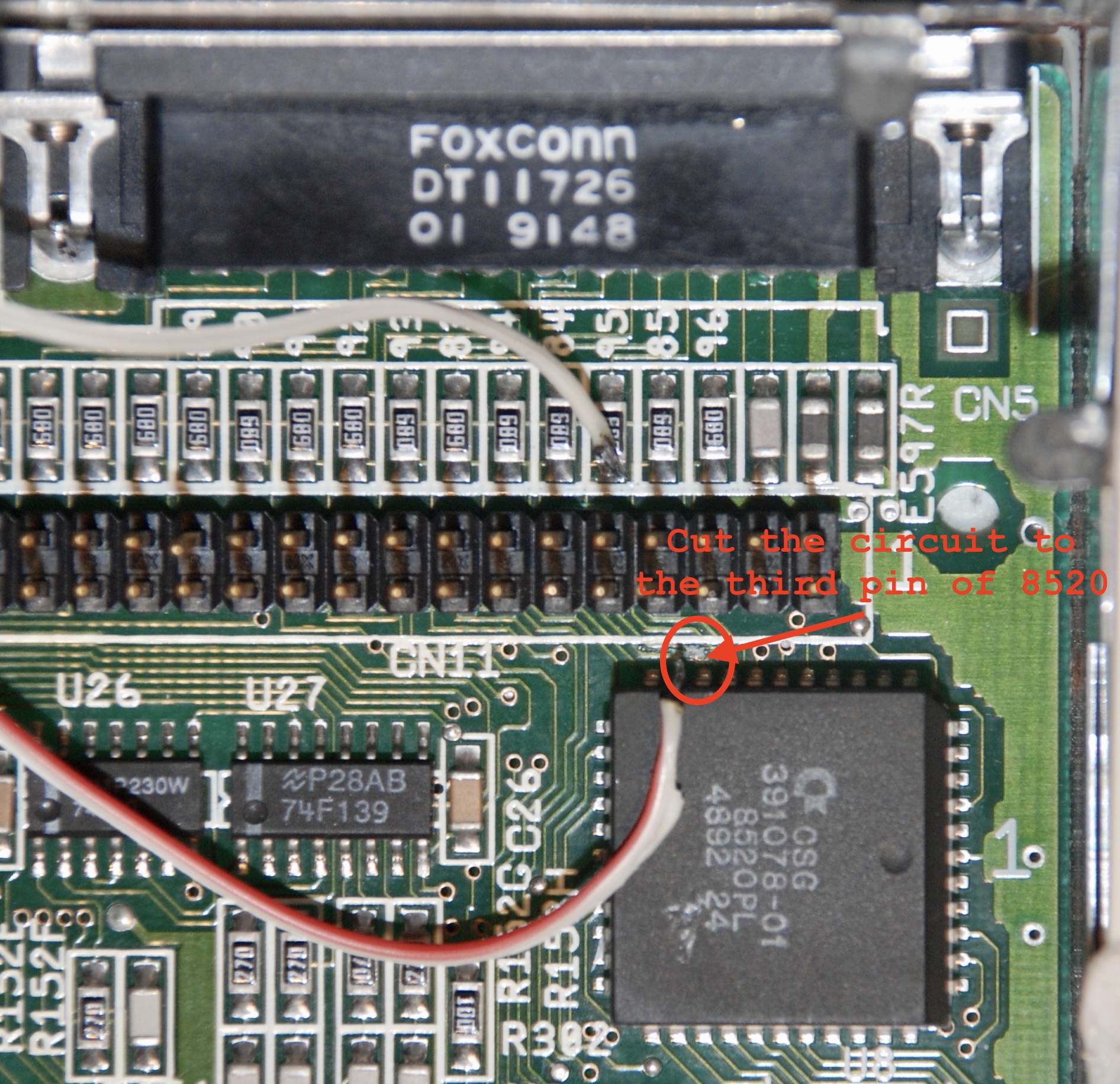
Separate SEL1 output of 8520 chip from the external drive input. Locate resistor E595 and cut the circuit that goes from this resistor to the 8520. This is below the resistor, to the left. Once cut, use a multimeter to verify that there is no connection between the resistor and the chip (see one of the pictures below which pin to check on the chip).
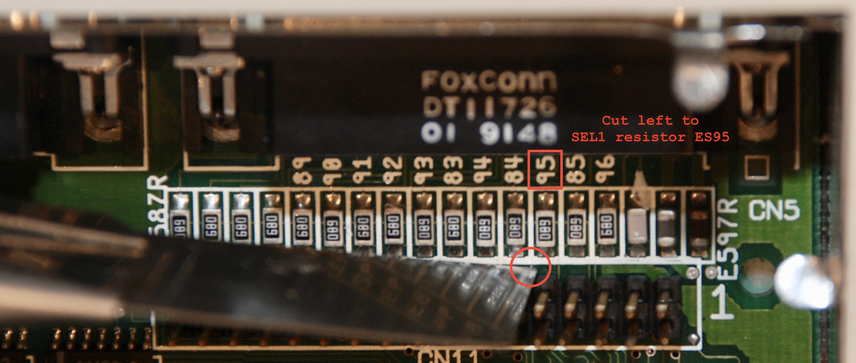
Solder a two-wire cable to the separated SEL1 input and output. Soldering points are:
- Lower terminal of the E595 resistor (cable 1A)
- 8520 SEL1 output pin: 2nd from the left (cable 1B).

Separate SEL0 output of 8520 chip from the SEL0 input of the internal drive connector.
Separate SEL0 output of 8520 chip from the SEL0 input of the Gayle chip
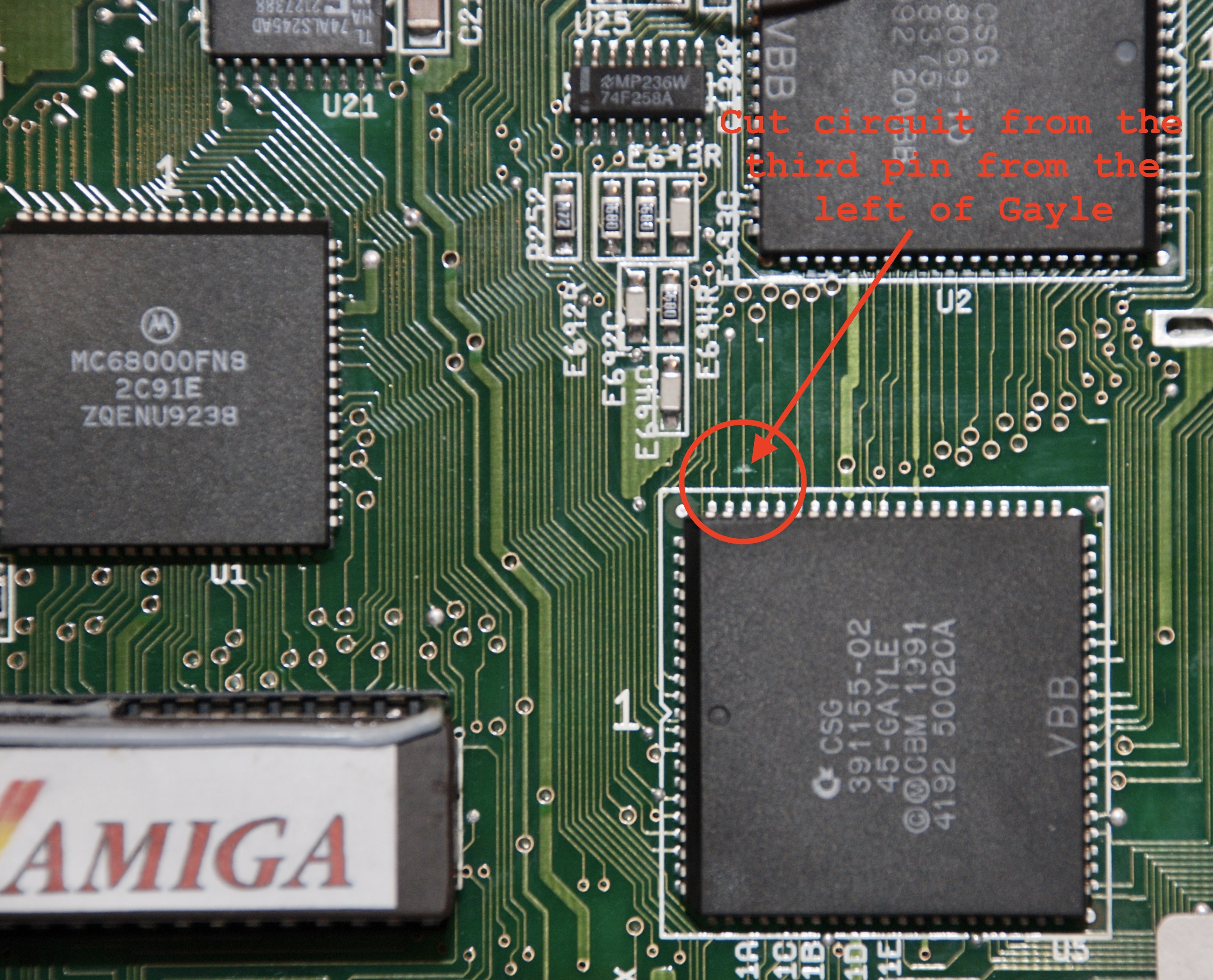
Solder a two-wire cable to the separated SEL0 inputs and output. Soldering points are:
- Gayle chip SEL0 input pin: 3rd from the left + floppy connector SEL1 input pin: lower row 5th from the right (pin #10) – connect both together (cable 2A)


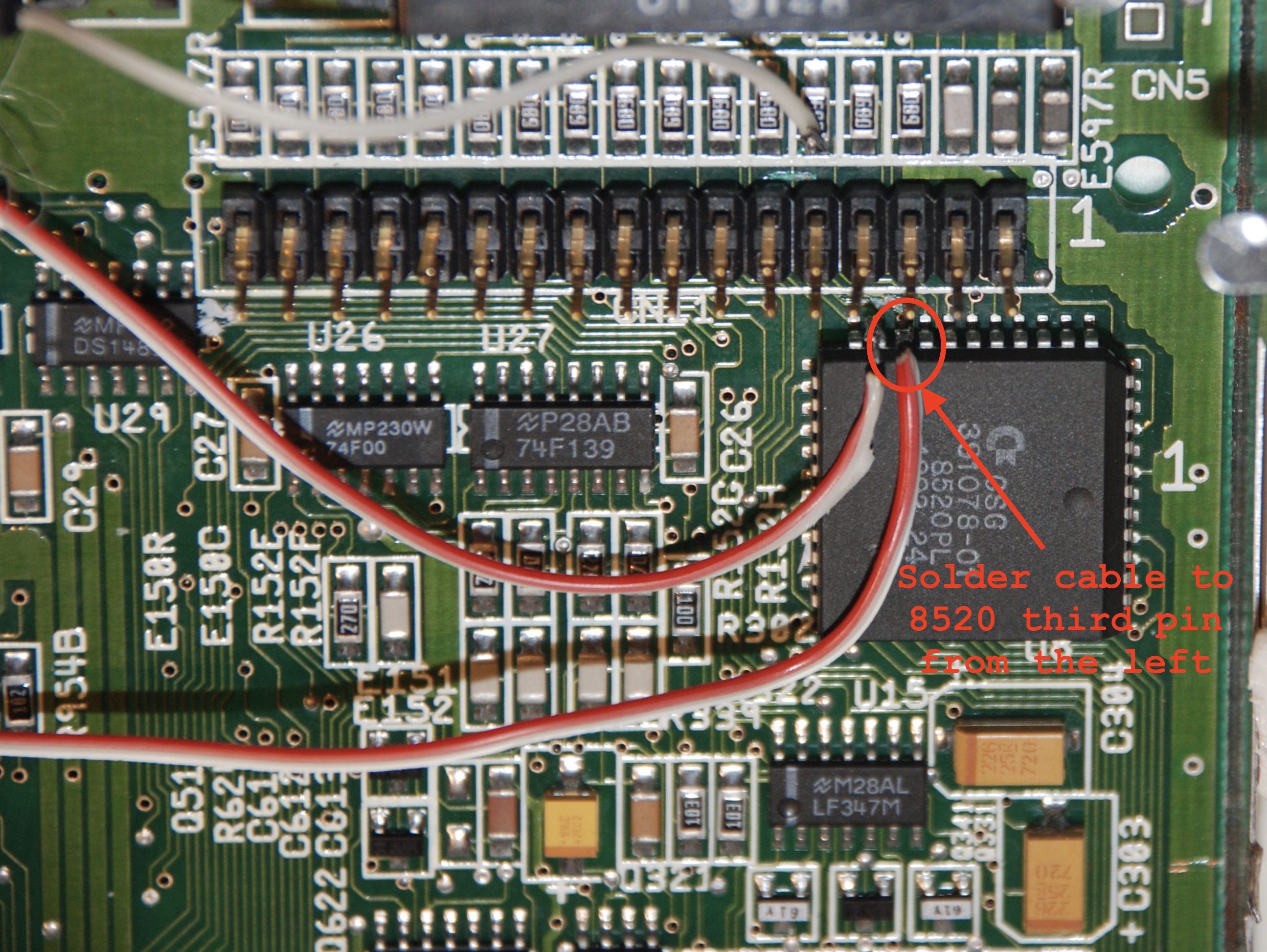
- 8520 SEL0 output pin: third from the left (cable 2B)
Install a double pole toggle switch. A good – and possibly the only – place is in the left upper corner of the case, facing down. The allocations of the cables to the switch poles are on the picture.
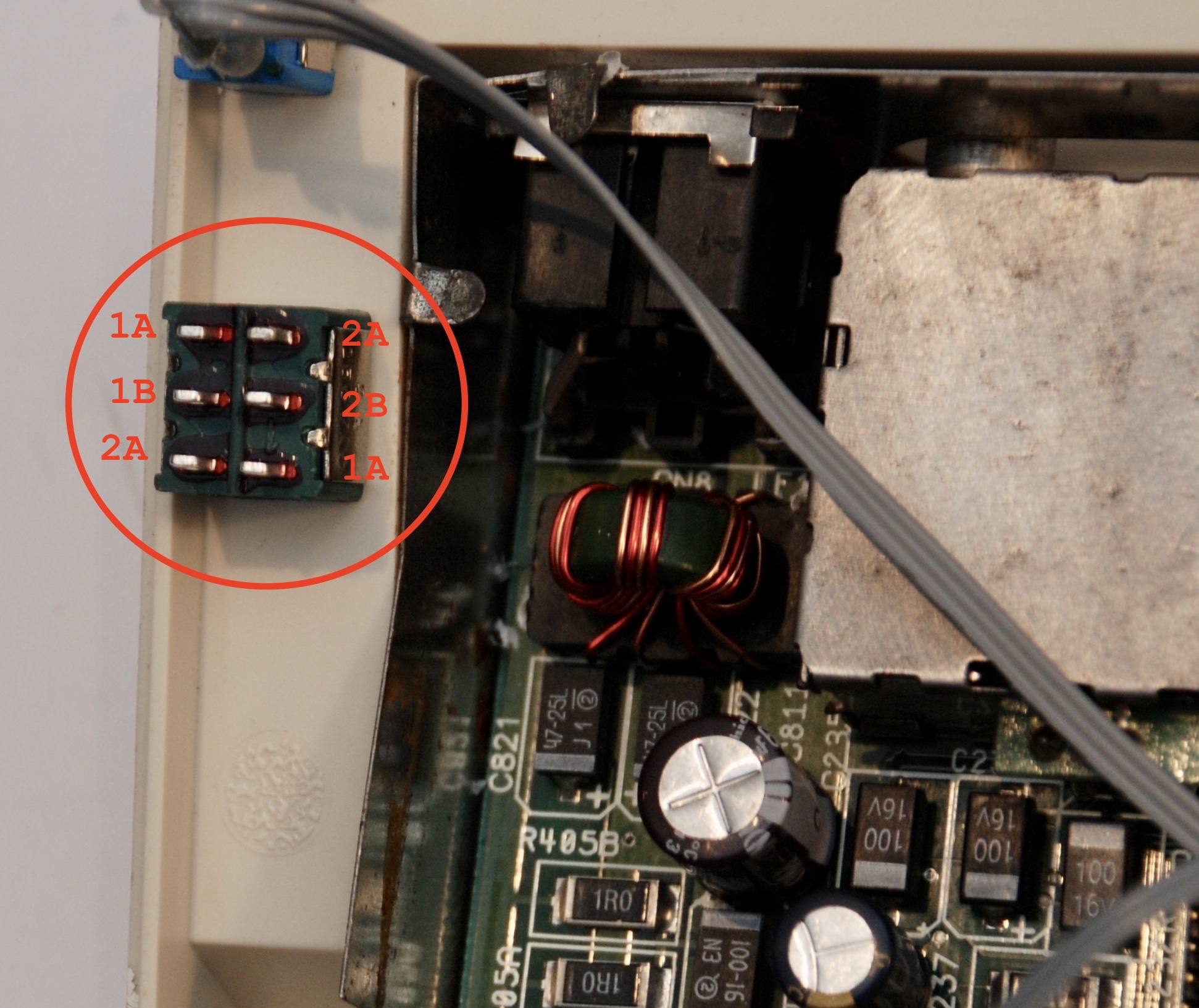
Solder the cables (1A, 1B, 2A, 2B) to the switch.


That’s it, put the Amiga together and enjoy your boot selector.