


Resources
Wiki
Amiga Store
Amiga Hardware Database
Documents
Internals


Video
Please see Video section of Amiga CDTV
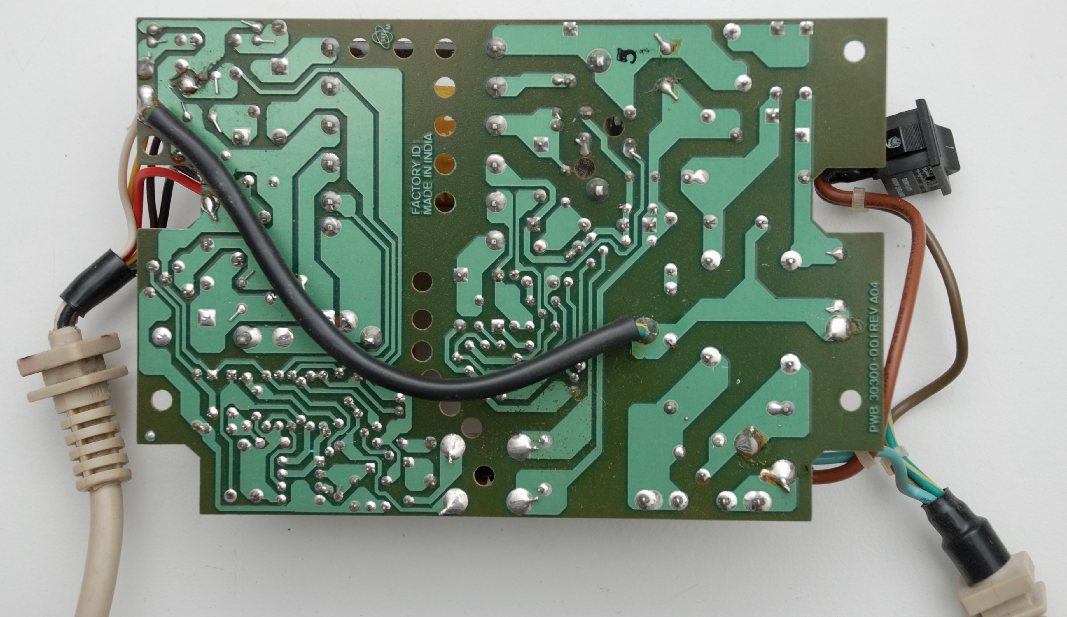
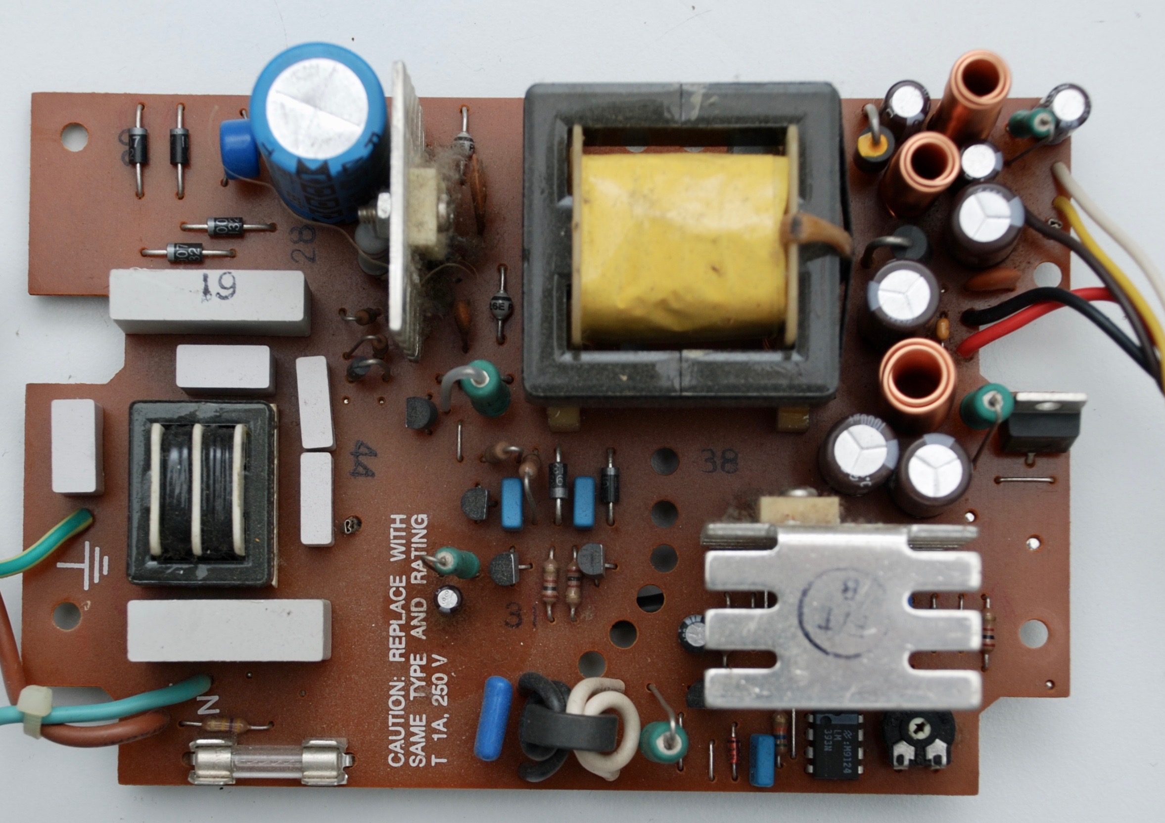
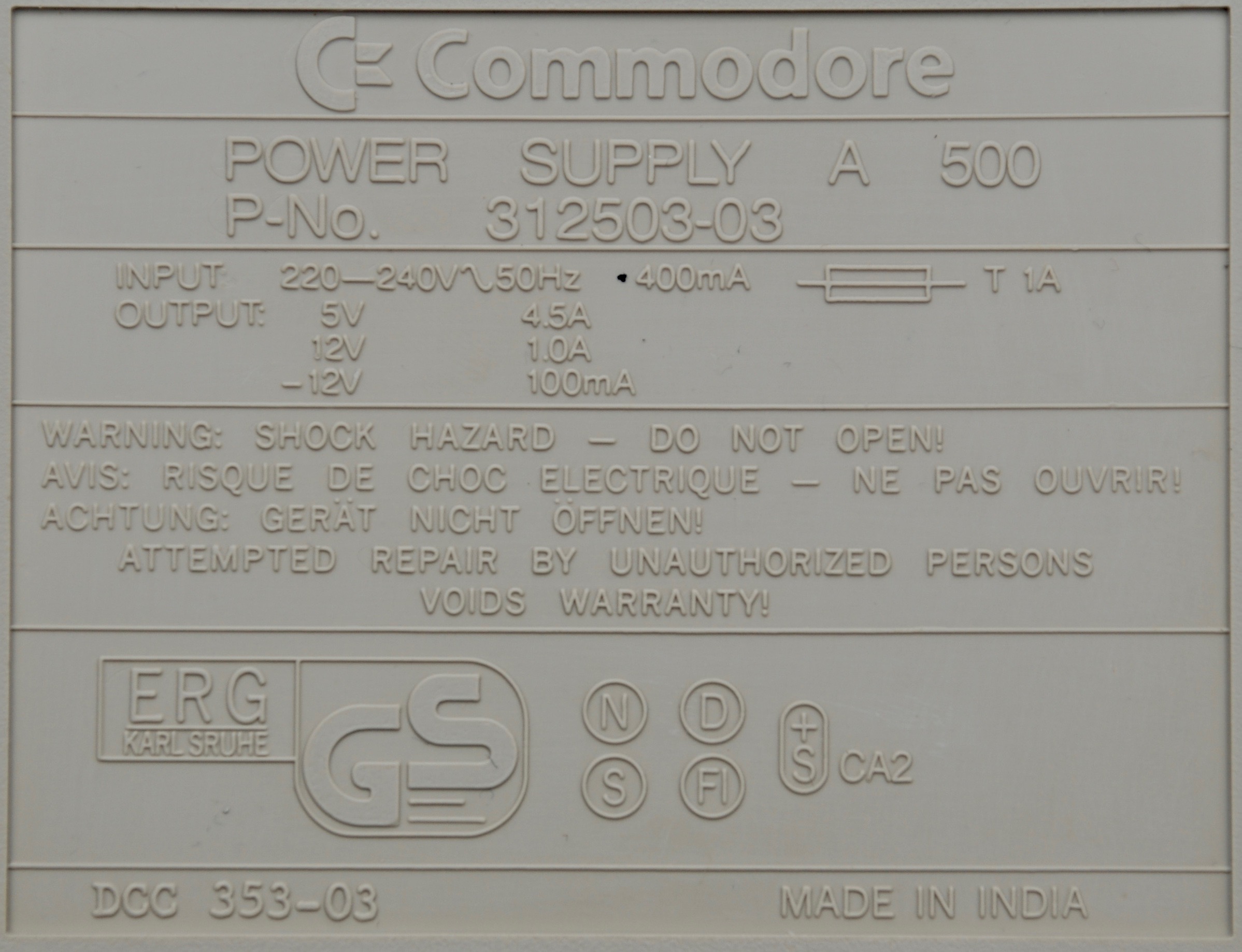
Power Supply


Bootselector – switching internal and external drives
Normally it is possible to boot Amiga 500 with Kickstart 1.3 from the internal floppy disk drive only (DF0). Booting from the external drive (DF1) becomes important for example when using Gotek USB drive in an external drive enclosure.
A boot menu is added from Kickstart 2.0, but even then, there are games and demos that have custom drive access routines that will default to DF0 and will refuse to load, even after a successful boot from the external drive.
To overcome these difficulties, it is possible to quite easily install a physical switch that will exchange DF0 and DF1 drives on a hardware level, so DF1 becomes DF0 and vice versa.
It is possible to connect up to four disk drives to Amiga, one internal and three external. They all sit on the same data bus/cable, that is routed to the internal drive connector on the motherboard and the external drive port on the back of the computer. In order to choose which drive own the bus for the data exchange, there are four independent drive selection lines (SEL0-SEL3). SEL0 is routed only to the internal drive connector, while SEL1-3 are available on the external port. Exchanging SEL0 with SEL1 will result in the external drive being physically visible as the internal and vice versa.
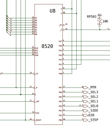
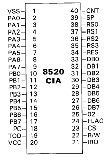
From the amigawiki.org schematic we can see that SEL0 line goes to PB3 output of 8502 CIA chip and SEL1 goes to PB4. In turn, the 8502 chip spec suggests that for DIP-40 package PB3 is on pin 13 and PB4 is on pin 14.
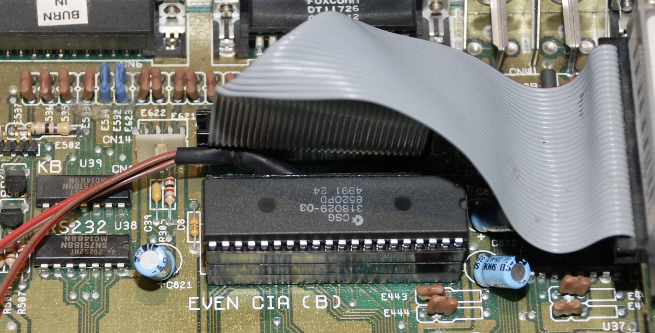
This chip is fortunately mounted on a socket, so we can easily remove it and add two extra sockets in which we will install the new pin routing. This will allow us to keep both the original socket and the chip unmodified.
We bend away pins 13 and 14 in one socket that will hold the chip. In another socket at the same pins location we carve out a bit of the plastic insulation so we can bend out the upper part of the pin connectors out of the socket.


We can solder a two wire cable to the pins in each of the sockets and insulate the cables.

Then we stack the sockets up, install on the original board socket and add the chip on top.
The cables, if connected straight, give the original drive assignment. When criss-crossed, drives DF0 and DF1 are exchanged. At the end, it is possible to install a switch that will do this for us.


3 Responses
[…] boot menu. For Amiga 500 with Kickstart 1.3 it is possible to boot from the external drive with an additional hardware mod. Below we will focus on how to install the Gotek drive in the external closure […]
[…] from the drives to the drive controller 8520 VIA chip. It is not so easy as in Amiga 500, where the chip is replaceable and sitting in a socket, still […]
[…] nostalgia. The 128 basically let me do programming on Basic – and it was great. I dabbled in the Amiga a bit later, but then grew into the PC mode a bit due to work. When I finally was able to use a PC […]